HYDRAULICS ( 670441 )
HYDRAULICS ( 670441 ). Philadelphia University Faculty of Engineering Civil Engineering Department First Semester, 2011/2012. Lecture Title. Water Flow in Open Channels. Introduction. An open channel is a duct in which the liquid flows with a free surface .

HYDRAULICS ( 670441 )
E N D
Presentation Transcript
HYDRAULICS(670441) Philadelphia University Faculty of Engineering Civil Engineering Department First Semester, 2011/2012
Lecture Title Water Flow in Open Channels
Introduction An open channel is a duct in which the liquid flows with a free surface. Open channel hydraulics is of great importance in civil engineers, it deals with flows having a free surface, for example: • Channels constructed for water supply, irrigation, drainage, and • Sewers, culverts, and • Tunnels flowing partially full; and • Natural streams and rivers. 3
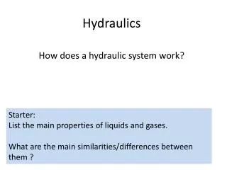
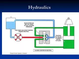
Pipe Flow and Open Channel Flow • Open Channel Flow • Flow takes place due to the slope of the channel bed (due to gravity). • The flow must be classified as open channel flow if the liquid has a free surface. Pipe Flow • The liquid completely fills the pipe and flow under pressure. • The flow in a pipe takes place due to difference of pressure (pressure gradient), • The flow in a closed conduit is not necessarily a pipe flow.
Open Channel Flow Pipe Flow
For Pipe flow (Fig. a): • The hydraulic gradient line (HGL) is the sum of the elevation and the pressure head (connecting the water surfaces in piezometers). • The energy gradient line (EGL) is the sum of the HGL and velocity head. • The amount of energy loss when the liquid flows from section 1 to section 2 is indicated by hL. For open channel flow (Fig. b): • The hydraulic gradient line (HGL) corresponds to the water surface line (WSL); where it subjected to only atmospheric pressure which is commonly referred to as the zero pressure reference. • The energy gradient line (EGL) is the sum of the HGL and velocity head. • The amount of energy loss when the liquid flows from section 1 to section 2 is indicated by hL. For uniform flow in an open channel, this drop in the EGL is equal to the drop in the channel bed.
6.1 Classifications of Open Channel Flow Classification based on the time criterion: • Steady Flow (time independent) (discharge and water depth do not change with time) • Unsteady Flow (time dependent) (discharge and water depth at any section change with time) Classification based on the space criterion: • Uniform flow (are mostly steady) (discharge and water depth remains the same at every section in the channel) • Non-uniform Flow (discharge and water depth change at any section in the channel)
Non-uniform flow is also called varied flow ( the flow in which the water depth and or discharge change along the length of the channel), it can be further classified as: • Gradually varied flow(GVF) where the depth of the flow changes gradually along the length of the channel. • Rapidly varied flow (RVF) where the depth of flow changes suddenly over a small length of the channel.
Unsteady uniform flows are very rare in nature • Uniform flow are mostly steady • Steady varied flow • (over a spillway crest) • Unsteady varied flow (flood wave) • Unsteady varied flow (tidal surge)
6.2 Uniform Flow in Open Channel Uniform flow in an open channel must satisfy the following main features: • The water depth y, flow area A, discharge Q, and the velocity distribution V at all sections throughout the entire channel length must remain constant. • The slope of the energy gradient line (Se), the water surface slope (Sws), and the channel bed slope (S0) are equal. Se = Sws = S0
This is possible when the gravity force (W sinq)component equal the resistance to the flow (Ff) The Chezy Formula
Rh = hydraulic radius or hydraulic mean depth • C = Chezy coefficient (Chezy’s resistance factor), m1/2/s, varies in relation of both the conditions of channel and flow. • Manning derived the following empirical relation: • where n = Manning’s coefficient for the channel roughness • See the next table for typical values of n.
Manning’s formula • Substituting into Chezy equation, we obtain the Manning’s formula for uniform flow: OR Where: • Q in m3/sec, • V in m/sec, • Rh in m, • Se in (m/m), • n is dimensionless
Example 1 Open channel of width = 3m as shown, bed slope = 1:5000, d=1.5m find the flow rate using Manning equation, n=0.025.
Example 2 The cross section of an open channel is a trapezoid with a bottom width of 4 m and side slopes 1:2, calculate the discharge if the depth of water is 1.5 m and bed slope = 1/1600. Take Chezy constant C = 50.
Example 2 Open channel as shown, bed slope = 69:1584, find the flow rate using Chezy equation, take C=35.
6.3 Hydraulic Efficiency of open channel sections Based on their existence, an open channel can be natural or artificial: • Natural channels: such as streams, rivers, valleys, etc. These are generally irregular in shape, alignment and roughness of the surface. • Artificial channels: built for some specific purpose, such as irrigation, water supply, wastewater, water power development, and rain collection channels. These are regular in shape and alignmentwith uniform roughness of the boundary surface.
Based on their shape, an open channel can be prismatic or non-prismatic: • Prismatic channels: the cross section is uniform and the bed slop is constant. • Non-prismatic channels: when either the cross section or the slope (or both) change, the channel is referred to as non-prismatic. It is obvious that only artificial channel can be prismatic. • The most common shapes of prismatic channels are rectangular, parabolic, triangular, trapezoidal and circular; see the next figure.
Most economical section is called the best hydraulic section or most efficient section as the discharge, passing through a given cross-sectional area A, slope of the bed S0 and a resistance coefficient, is maximum. • Hence the discharge Q will be maximum when the wetted perimeter P is minimum.
Economical Rectangular Channel P should be minimum for a given area; So, the rectangular channel will be most economical when either: the depth of the flow is half the width, or the hydraulic radius is half the depth of flow.
Other criteria for economic Trapezoidal section • When a semi-circle is drawn with the trapezoidal center, O, on the water surface and radius equal to the depth of flow, D, the three sides of the channel are tangential to the semi-circle”. • To prove this condition, using the figure shown, we have: using triangle KMN, we have:
using equation to replace the numerator , we obtain: Thus, if a semi-circle is drawn with O as center and radius equal to the depth of flow D, the three sides of a most economical trapezoidal section will be tangential to the semi-circle.
Now, from equations: squaring both sides The best side slope is at 60o to the horizontal, i.e.; of all trapezoidal sections a half hexagon is most economical. However, because of constructional difficulties, it may not be practical to adopt the most economical side slopes
Circular section In the case of circular channels, the area of the flow cannot be maintained constant. Indeed, the cross-sectional area A and the wetted perimeter P both do not depend on D but they depend on the anglea. Referring to the figure shown, we can determine the wetted perimeter P and the area of flow A as follows: • Thus in case of circular channels, for most economical section, two separate conditions are obtained: • Condition for maximum discharge, and • Condition for maximum velocity.
Condition for Maximum Discharge for Circular Section: (Using the Chezy formula) (Using Manning’s formula) • Condition for Maximum Velocity for Circular Section:
6.4 Energy Principle in Open Channel Flow The total energy of a flowing liquid per unit weight is given by: If the channel bed is taken as the datum, then the total energy per unit weight will be: Specific energy(Es)of a flowing liquid in a channel is defined as energy per unit weight of the liquid measured from the channel bed as datum. It is a very useful concept in the study of open channel flow.
Ep = potential energy of flow = y Ek= kinetic energy of flow = Valid for any cross section Specific Energy Curve: It is defined as the curve which shows the variation of specific energy (Es ) with depth of flow y.
Specific Energy Curve (Rectangular channel) Considera rectangular channel in which a constant discharge q = discharge per unit width = = constant ( since Q and B are constants) EK Es EP yc
T T Sub-critical, critical, and supercritical flow The criterion used in this classification is what is known by Froude number, Fr, which is the measure of the relative effects of inertia forces to gravity force: V = mean velocity of flow of water, Dh = hydraulic depth of the channel
Referring to the energy curve, the following features can be observed: • The depth of flow at point C is referred to as critical depth, yc. • (It is defined as that depth of flow of liquid at which the specific energy is minimum, The flow that corresponds to this point is called critical flow (Fr = 1.0). • For values of Es greater than Emin , there are two corresponding depths. One depth is greater than the critical depth and the other is smaller then the critical depth, for example; These two depths for a given specific energy are called the alternate depths. • If the flow depth the flow is said to be sub-critical (Fr < 1.0). In this case Es increases as y increases. • If the flow depth the flow is said to be super-critical (Fr > 1.0). In this case Es decreases as y increases.
Critical depth, yc for rectangular channel Critical depth, yc , is defined as that depth of flow of liquid at which the specific energy is minimum, Emin, The mathematical expression for critical depth is obtained by differentiating energy equation with respect to y and equating the result to zero;
Critical depth, yc, for Non- Rectangular Channels OR (constant discharge is assumed) dA/dy = the rate of increase of area with respect to y = T (top width). condition must be satisfied for the flow at the critical depth. Recalling that The equation may also be written in terms of velocity The velocity head is equal to one-half the hydraulic depth for critical flow.
This equation represents the critical state The general equation for the specific energy in critical state applicable to channels of all shapes. OR Rectangular section Trapezoidal section Circular section Triangle section
Constant Specific Energy The specific energy was varied and the discharge was assumed to be constant. Let us now consider the case in which the specific energy is kept constant and the discharge Q is varied. The discharge will maximum if dA/dy = T
but Thus for a given specific energy, the discharge in a given channel is a maximum when the flow is in the critical state. The depth corresponding to the maximum discharge is the critical depth.
6.5 Hydraulic Jump • A hydraulic jump occurs when flow changes from a supercritical flow (unstable) to a sub-critical flow (stable). • There is a sudden rise in water level at the point where the hydraulic jump occurs. • Rollers (eddies) of turbulent water form at this point. These rollers cause dissipation of energy. • A hydraulic jump occurs in practice at the toe of a dam or below a sluice gate where the velocity is very high.
General Expression for Hydraulic Jump: In the analysis of hydraulic jumps, the following assumptions are made: (1) The length of hydraulic jump is small. Consequently, the loss of head due to friction is negligible. (2) The flow is uniform and pressure distribution is due to hydrostatic before and after the jump. (3) The slope of the bed of the channel is very small, so that the component of the weight of the fluid in the direction of the flow is neglected.
Location of hydraulic jump • Generally, a hydraulic jump occurs when the flow changes from supercritical to subcritical flow. • The most typical cases for the location of hydraulic jump are: • Jump below a sluice gate. • Jump at the toe of a spillway. • Jump at a glacis. • (glacis is the name given to sloping floors provided in hydraulic structures.)
The net force in the direction of flow = the rate of change of moment in that direction The net force in the direction of the flow, neglecting frictional resistance and the component of weight of water in the direction of flow, R = F1 - F2 . Therefore, the impulse-moment yields Where F1 and F2are the pressure forces at section 1 and 2, respectively. = the distance from the water surface to the centroid of the flow area
Comments: • This is the general equation governing the hydraulic jump for any shape of channel. • The sum of two terms is called specific force (M). So, the equation can be written as: • M1 = M2 • This equation shows that the specific forcebefore the hydraulic jump is equal to that after the jump.