Download
1 / 37
380 likes | 539 Vues
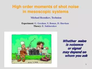
High order moments of shot noise in mesoscopic systems. Michael Reznikov, Technion. Experiment: G. Gershon, Y. Bomze, D. Shovkun Theory: E. Sukhorukov. Whether noise is noisence or signal may depend on whom you ask. f. Classical Shot Noise. S( ). I. w=1/ f. t. .

E N D
High order moments of shot noisein mesoscopic systems Michael Reznikov, Technion Experiment: G. Gershon, Y. Bomze, D. Shovkun Theory: E. Sukhorukov Whether noise is noisence or signal may depend on whom you ask
f Classical Shot Noise S() I w=1/f t
Noise in mesoscopic systemsscattering approach Khlus (1987), Lesovik (1989), Yurke and Kochansky (1989)
Fractional Quantum Hall Effect- Experimental Results Rxy (h/e2) Rxx (kW) Magnetic Field (T) J. Smet, V. Umansky
Expected Noise…..(intuitively) = 1/3 q = e ; whole electrons partitioning barrier quasi particles partition e t e/3 e/3 t e/3 q = e/3 ; quasi particles Both,eore/3 lead to the same conductance ! whole electrons partition
Quantum Shot Noise in QPC - Experimental Results - /Hz) 6 2 A T=57 mK -28 G=0.37 (10 4 I i 2 Current Noise, S 0 0 1 2 3 Total Current (nA)
Current Noise Measurements at nbulk=1/3 ns=1.1x1011 cm-2 ; B=13 T /Hz] 7 e 2 e/3 A 6 -29 G=0.82 [10 5 4 G=0.73 Current Noise, S 3 2 0 200 400 Back-scattered Current, I [pA] r • preamp noise subtracted • calibration at each point • averaging time 4 s • Lesovik’s formula, q=e/3 I=tVg0 /3 See also : Saminadayar et. al. 1997 Ir=V(g0/3-g)
e/5 B=2/5 t=0.86 T=85 mK e/3 Current Noise, S[10-30 A2/Hz] Conductance, g/g0 Back-Scattered Current, Ir [pA] Quantum Shot Noise at =2/5 - Weak Back Scattering - =2/5 q=e/5 ! Ir=V(2g0 /5-g)
Is this what is really measured? At least not always S(ω)! Lesovik, Loosen (1997)
1 Naïve calculations b a
1 Naïve calculations For G~0 does not reproduce Poisson result q3=g0V =eI !
“Gentle” electron counting Spin 1/2 as a galvanometerL.S. Levitov and G.B. Lesovik (1993) L.S. Levitov and H. Lee (1996)
“Gentle” electron counting Spin 1/2 as a galvanometerL.S. Levitov and G.B. Lesovik (1993) L.S. Levitov, H. Lee, G. Lesovik (1996) U=eV/T
n=20 Gaussian vs. Poisson distributions In our measurements n~1000
Khlus (1987), Lesovik (1989), Yurke and Kochansky (1989) L.S. Levitov and G.B. Lesovik (1993) L.S. Levitov and H. Lee (1996) Intrinsic cumulants for a single channel conductor (G=0.5)
Experimental results from Yale B. Reulet, J. Senzier and D. E. Prober, 2002
and in QPC Filling factor =4 T=4.2 K ~0.3
V0 V Z sample CV Cst Rl 1 How to measure? Opening and closing of the barrier I. Klich, 2001 What is actually measured?
Zs>>Zl – voltage bias V0 V Z sample CV Cst Rl K. Nagaev – cascade corrections Kindermann, Nazarov, Beenakker (2002)
Zs<<Zl – current bias V0 V Z sample CV Cst Rl
General case for a tunneling junction<<1, T<<eV In general: Kindermann, Nazarov, Beenakker (2002)
and in QPC Filling factor =4 T=4.2 K ~0.3 26
Network analyzer Cc I QPC N Cv Cst Vg Rl A/D Low temperature Experimental Setup
“Intrinsic” contribution t3 t t2 t1 A(t) J(t) “Intrinsic” (constant voltage) contribution
A(t) Z(t) J(t) Corrections, “environmental” and nonlinear t2 t1 t
Environmental correction is not small! If we ignore peculiarities of the circuit -mostly determined by the load thermal noise Not small even when R! 0
QPC characterization T=1.5K
Calculation of the statistics T-ordering is to put q(0) to the right of q(t) Using e.g. wave packet approach one can get the statistics (Levitov, Lesovik, 1993)
How to express it through the integral of the currents (Bachman, Graf, Lesovik, 2009) Consider a slightly different object Properties: Q3=0 if one of ti=0. Therefore it can be expressed as: Time ordering is crucial to ensure Q3=0 for ti=0 !!! 37
“Contact” terms Differentiation ovet t1 would generate 2 more -functions, provided [q,j] 0. So, there are additions to the term accounted for in naïve calculations: h j(t1) j(t2) j(t3)i 38
My favorable choice of j b a L 1 Compare with: 39
Conclusions and questions • Prediction for <<J3>> in QPC is verified • Effect of interactions on <<J3>>. • Charge statistics under FQHE? • Charge statistics in HTC superconductors • <<J3>> in diffusive systems with interactions • Frequency dependence of <<J3>>. 40