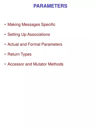
FEL Parameters
FEL Parameters. D. Schulte. Goals for Today. Define some baseline to work on Energy goal Will probably change later But good to have something that you can criticise Identify key questions for the other groups Plan the integrated studies Which studies can we perform before February?

FEL Parameters
E N D
Presentation Transcript
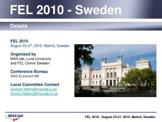
FEL Parameters D. Schulte D. Schulte, CERN, October 2013
Goals for Today • Define some baseline to work on • Energy goal • Will probably change later • But good to have something that you can criticise • Identify key questions for the other groups • Plan the integrated studies • Which studies can we perform before February? • What needs to be done afterwards? • What can be analytical? • Where are simulations required? • Who does what? • Exchange news D. Schulte, CERN, October 2013
Some News • We will develop an improved cost model for the klystron-based CLIC • Igor reviewed RF unit cost • GermanaRiddone (and Philippe Lebrun) will review scaling of cost with numbers and cost of the linac • This can be applied nicely to the FEL • Some small differences exist (e.g. no damping) • Discussion with Marco Pedrozzi (PSI) indicated interest in O(15keV) photons (sub-Angstrøm) • We announced the activity in the CLIC project meeting D. Schulte, CERN, October 2013
Energy Target • What is the energy range at the end of the linac? • Is the maximum 0.07nm or 0.15nm? • Are the bunch parameters the same for different energies? • lower energy implies lower gradient (or additional extraction points) • lower gradient changes the longitudinal and transverse wakefield effects • either need more margin in linacwakefields • or need to only change gradient in Linac3, but have to check longitudinal effects • Need to understand operation at lower energy • Who finds out which range is required? D. Schulte, CERN, October 2013
Repetition Rate and Bunch Number • Baseline is 50Hz, single bunch • For beam dynamics there is no difference to 500Hz, single bunch • For a few bunches per train, we have to check wakefield effects • Who will do this (in the linac group?)? • 500Hz, single bunch means higher heat load in the structures and puts constraints on the injector • The groups will address the issue • 500Hz, multi-bunch will not change much for the linac RF but might change things for the injectors • The groups will address the issue D. Schulte, CERN, October 2013
Longitudinal Dynamics E [MeV] E [MeV] E [GeV] • Longitudinal design needs to be optimised keeping in mind the transverse effects • shorter bunches in linac2 reduce transverse wakefield effects • Fast optimisation routine is required (Andrea did it for one structure) • Some photon production model is needed (Avni did some work, but can we have something analytical?) • Who can put together a fast longitudinal model? D. Schulte, CERN, October 2013
Transverse Dynamics Stability requires • Transverse effects are also critical • Have simplified model for the main linac (partly analytical) • But need to also understand impact on photon production • Do we need a simulation? Do we have some analytic estimates? • In the long run need full 6D simulation • Who can check analytical estimates for photon production/rules of thumb? • Who will start to integrate 6D simulations? D. Schulte, CERN, October 2013
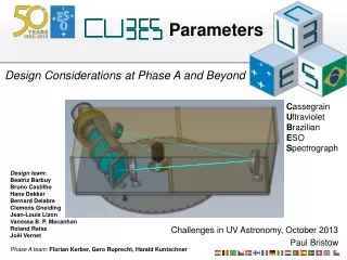
Preliminary Structure Choice? Preliminary a1/λ=0.15, a2/λ=0.1 d1/λ=0.9mm, d2/λ=1.7mm L=0.75m, G=65MV/m Pin=41.8MW, τ=149.6ns 11 RF units 11 structure per unit? Cost=49.7 a.u. This structure has happened to be the cheapest Should we use it as a GUINEA-PIG to set up the simulations? D. Schulte, CERN, October 2013
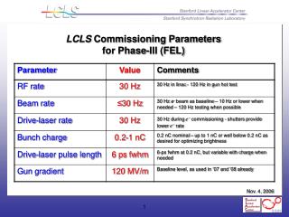
Electron linac RF unit layout based on the existing (industrialized) RF sources (klystron and modulator) 2x ScandiNova solid state modulators 2x CPI klystrons 410 kV, 1.6 s flat top 50 MW 1.5 s (Operated @45MW) I. Syratchev, modified by me X 5.2 100 (90) MW 1.5 s ~11 m, 16.3 cm TE01 transfer line (RF=0.9) Inline RF distribution network TE01 900 bend Common vacuum network Preliminary 468 MW (418 MW) 150 ns x 10 accelerating structures @68.8MV/m (65MV/m) 46.8MV (41.8MW) input power 10 m, 7.5 active This unit should provide ~516 (488) MeV acceleration beam loading. Need 12 (12) RF units. Cost 51.7 a.u., 4% more than optimum D. Schulte, CERN, October 2013
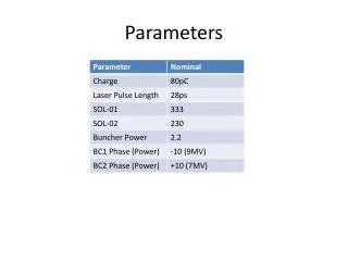
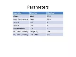
More Examples for Basic Parameters Preliminary D. Schulte, CERN, October 2013
Conclusion • Will try to put names to the tasks • Energy range choice • Energy range operation considerations • Simplified longitudinal model • Simplified transverse model/considerations • Complete longitudinal and transverse model D. Schulte, CERN, October 2013