Decoherence Dynamics of a Qubit in Fluctuating Environments: Free and Driven Evolution
This paper explores the decoherence processes affecting a qubit during free and driven evolution in fluctuating environments. We analyze persistent currents in a split Cooper pair box known as the Quantronium, highlighting how noise impacts qubit relaxation and dephasing. Our findings include the evaluation of readout fidelities and the implications of different readout methods (DC vs. RF). We also demonstrate the robustness of qubit manipulation techniques through Rabi oscillations and composite pulse sequences, providing insights into qubit control and coherence time optimizations.

Decoherence Dynamics of a Qubit in Fluctuating Environments: Free and Driven Evolution
E N D
Presentation Transcript
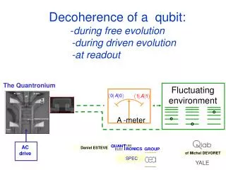
Fluctuating environment 1 0 AC drive Decoherence of a qubit: -during free evolution -during driven evolution -at readout A -meter Daniel ESTEVE of Michel DEVORET SPEC YALE
qubit relaxation noise DECOHERENCE DURING FREE EVOLUTION dephasing DEPHASING
2 knobs : U 2 energies: F Statedependent persistent currents i The quantronium: 1) a split Cooper pair box 1 d° of freedom
hn01 readout + environment weaker dephasing at optimal point 2) protected from dephasing energy (kBK) n01(GHz) d/2p d/2p Ng Ng EJ=0.86 kBK EC=0.68 kBK
Readout of persistent currents with dc switching 1: switching 1 0: no switching 0 discrimination 3) with a readout junction d/2p Ng
Qubit control: Rabi precession switching probability (%) Rabi oscillations c Y Effective field X nµw rotation wRabi = aURF
Readout fidelity ? 40% contrast (only)
Qubit manipulation Z Y X arbitrary transformations adiabatic frequency pulses for Z rotations robust transformations Composite ‘ p ’ CORPSE : 60°X 300°-X 420 X° ‘ p ’ CORPSE Single pulse
n01(GHz) optimal point Ng=1/2 , d=0 Ng drive d/2p d Ng no dephasing no current nA minimum relaxation due to d Ng Decoherence sources in the quantronium circuit d
a + environment Pure dephasing b not necessarily exponential Decoherence in the Quantronium d Relaxation P0 if balanced junction !
Model for dephasing: charge and phase noise d DNg ou Dd (linear coupling) Spectral density
p t Relaxation of the Quantronium P0 T1=0.5µs T1: 0.3-2 ms
wRabi wRabi w=w01-wRF Projection Z readout p/2 pulse p/2 pulse Free evolution (rotation also) Ramsey interferences Ramsey interferences reveal decoherence of free evolution during the delay
Characterizing dephasing: 1) decay of Ramsey fringes Dt Fit Dn = 19.84 MHz T2 = 500 +/- 50 ns best ones: nRF= 16409.50 MHz
typical sample Fit with the linked cluster expansion: static approximation ( Makhlin Shnirman, Paladino, Falci)
Comparing fits “static” approximation ( Makhlin Shnirman, Paladino, Falci) Simple exponential gaussian noise model 500 ns
n01(GHz) d/2p Nc away from optimal point Coherence time 0.028 0.028 0.028
p/2X p/2X Characterizing dephasing: 2a) phase detuning pulses Dt1 p/2X p/2X Dt2
p p/2 p/2 5) Probing the dynamics: spin echo experiments
p/2 p/2 p p/2 p/2 p/2 p/2 p Direct mapping of echo amplitude low frequency noise
Comparison exp vs model noise spectral densities Sd SNg Gaussian model 1/w 1/w w w 4MHz 0.5MHz non gaussian character of noise ?? Conclusion: decay times ok, not time dependence See G. Ithier et al.: Decoherence in a quantum bit Superconducting circuit circuit, preprint
d Ng Ng d [S(w)] 1/f 1/f [w] (Hz) [w] (Hz) Closer look at charge and phase spectral densities: Phase noise Charge noise Partly external Cut-off at .5 MHz
Driven at wRabi Decoherence: driven evolution versus free evolution Bloch-Redfield description Free See preprint on decoherence G. Ithier et al.
p/2X p/2X p/2X p/2X aY : Spin locking Determination of T*1
Determination of T*2 : Decay of Rabi oscillations with Rabi frequency
Decay of Rabi oscillations with frequency T*2 ~ 480 ns
decoherence in the rotating frame ? Z Y X Z I1*> I0*> drive lab frame: Ramsey decay: T2=300ns rotating frame: T2*=480 ns Conclusion: more robust qubit encoding in the rotating frame
Fluctuating environment 1 0 Decoherence at readout: projection fidelity ? ideal QND readout: Readout: 1 Readout: 0 errors: wrong answer + projection error A -meter
U d Decoherence :dc versus rf readout dc readout V resets the qubit dc pulse switching • simple, but: • rep rate limited by quasiparticles • qubit reset : NOT QND
U d Decoherence :dc versus rf readout PULSE IN rf readout (M. Devoret, Yale) PULSE OUT U d “RF” pulse dc pulse switching ddynamics in anharmonic potential • simple, but: • -fidelity 40% • qubit reset : NOT QND more complex, but: -better fidelity ? -no reset: possibly QND
Phase oscillations in a state dependent anharmonic potential Drive Ui I0 C g d V Ur Vg Output LC oscillator GUr 180° -180° 1.5 Frequency (GHz) (I. Siddiqi et al., PRL 93, 207002 (2004)) Qubit control port The Josephson Bifurcation Amplifier : latching OSCILLATION AMPLITUDE MICROWAVE DRIVE AMPLITUDE
Microwave readout setup MicroWave Generator RFin LO V demodulator 300 K S G=40dB M Pulsing I Q Vg TN=2.5K G=40dB -20dB 4 K -20dB LP 3.3GHz -30dB -30dB 600 mK 1 kW 4 kW 20 mK HP 1.3GHz LP 2GHz Directionnal coupler 50 W 50 W Sample from Yale
tin>150ns 100ns frequency: 1.4GHz Rabi oscillations 5ns Readout contrast? Bifurcation probability P Pulse duration (ns) Microwave power (dBm, top) (best dc switching: 60%) Readout : 50% contrast (Yale: 60%)
QND readout ? ppulse on qubit nopulse on qubit Readout 1 Readout 1 Readout 2 OR analysis yields for a single readout: Answer 1 Answer 0 Answer 1 Answer 1 Answer 0 Answer 0 partially QND (Yale & Saclay)
QND readout with an ac drive at optimal point ? flux qubit charge qubit quantronium SQUID inductance box capacitance JBA TU Delft, Helsinki (for SSET) Yale Saclay partially QND (in progress) Chalmers Readout fidelity & QND readout are (still) issues
Fluctuating environment 1 0 This work on : the Quantronium dc gate dc gate µw qp box trap A -meter readout junction 1µm SPEC Appl. Physics YALE I. SIDDIQI F. PIERRE E. BOAKNIN L. FRUNZIO G. ITHIER E. COLLIN P. ORFILA P. SENAT P. JOYEZ D. VION P. MEESON D. ESTEVE A. SHNIRMAN G. SCHOEN Y. MAKHLIN F. CHIARELLO R. VIJAY C. RIGETTI M. METCALFE M. DEVORET Karlsruhe Landau Roma remind: 10-4 error rate on qubit gates…, QND useful but not mandatory
Qubit in ground state
Quantum Non-Demolition Fraction pulse Readout 1 (R1) Readout 2 (R2) 5ns 100ns 20ns 125ns 20ns 30ns Ps(R1) Ps(R2) Ps(R1R2) Ps(R2/R1) 17.6% 13.3% 3.3% 18.8% no pulse pulse 61.3% 28.0% 19.1% 31.1% T1=1.3 s QND Frac.