Download
1 / 49
500 likes | 964 Vues
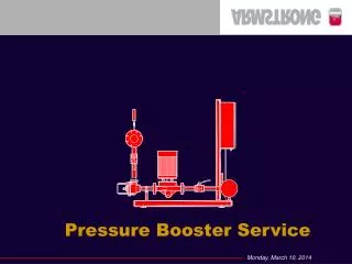
Pressure Booster Service. Booster Service Basics. Control Panel Components Setting a pressure switch Setting a current relay Adjusting the Easy PLC Relay Understanding and Adjusting a PRV. Control Panel Components. High Voltage: Disconnect, Starters, Overloads, Transformer

E N D
Booster Service Basics • Control Panel Components • Setting a pressure switch • Setting a current relay • Adjusting the Easy PLC Relay • Understanding and Adjusting a PRV
Control Panel Components • High Voltage: Disconnect, Starters, Overloads, Transformer • Low Voltage: Current Relays, PLC, pressure switches
Setting Overloads • Factory Set • Verified in the field
Pressure Switch Basics • Pressure switches have a Set Point and Re-Set • Re-set value always below the Set Point • Set Point and Re-Set are dependant on the purpose of the pressure switch
Pressure Switch Adjustment Differential Adjustment Set Point Adjustment PSI Scale Reading
Pressure Switch Adjustment • Differential Setting 4-150 Psig switch • Differential Setting 6-250 Psig switch
Pressure Switch Applications • Low suction pressure protection • No-Flow shutdown pump call on • Pump sequencing control • High and low pressure alarms
Low Suction Pressure Protection • Purpose: Stop pump in case of low inlet pressure • Set Point (Cut-In): 15 PSI - Pump Start • Re-Set (Cut-Out): 5 PSI - Pump Stop • differential: 10 PSI
No-Flow Shutdown Pump Call-On • Purpose: Start pump on drop in system pressure • Set Point (Cut-Out): 5 PSI below system pressure - Pump Off • Re-Set (Cut-In): 6 PSI - Pump On • differential: 1 PSI
Pump Sequencing Control • Purpose: Start pump on drop in system pressure • Set Point (Cut-Out): 5 PSI above system pressure - Pump Off • Re-Set (Cut-In): 5 psi below system pressure - Pump On • differential = (cut- in) - (cut - out)
High Suction Pressure Alarm • Purpose: Stop pump if inlet pressure is sufficient to supply building • Set Point (Cut-Out): @ approx. system pressure - Pump Off • Re-Set (Cut-In): approx. 5-10 PSI below system pressure - Pump On • differential: 5-10 PSI
Low System Pressure Cut-Out Alarm • Purpose: Stop pump if outlet pressure is too low • Set Point (Cut-In): approx. 5-10 PSI below system pressure - Pump On • Re-Set (Cut-Out): 30 PSI below system pressure- Pump Off • differential: 20-25 PSI
Low System Pressure Next Pump Starts Alarm • Purpose: Start next pump if outlet pressure is too low. Requires manual reset • Set Point (Cut-In): approx. 5-10 PSI below system pressure - Pump On • Re-Set (Cut-Out): 30 PSI below system pressure - Pump Off • differential: 20-25 PSI
High System Pressure Cut-Out Alarm • Purpose: Stop pump if outlet pressure is too high • Set Point (Cut-Out): 20 PSI above system pressure - Pump Off • Re-Set (Cut-In): System Pressure - Pump On • differential: 20 PSI
Current Relay Adjustment • On-Delay Time Scale (0-1) & (0-30)
Current Relay Adjustment • On-Delay Time Setting
Current Relay Adjustment • Threshold (Ie Value)
Current Relay Adjustment • Hysteresis - not used - set to zero
Easy PLC Relay • Contains sequencing logic for pump sequencing • Alarm condition activation • Timer values
Easy PLC Relay • Program written in ladder logic • Program changes require a programming device • Does not require in-field adjustment • Program access is password protected
Setting Timer • Select parameters • Toggle timer value required • Change timer value by pressing arrow
PRV Components Piloting Assembly Main Body Valve
PRV Components Speed Control Pressure Regulator Check Valve Check Valve • Diaphragm • Stem assembly • Sealing Ring • Valve Seat
PRV Control Logic • Outlet pressure of the valve is controlled by the pilot mounted PRV • Spring setting in PRV pilot determines outlet pressure of the main PRV • Turning PRV nut clockwise (down) will cause outlet pressure of main valve to increase
PRV Control Logic Large Area Small Area
PRV Control Logic CHECK CLOSED Opening the pilot relieves pressure on top of the diaphragm opening the main valve. CHECK CLOSED
PRV Control Logic CHECK CLOSED Closing the pilot increases pressure on top of the diaphragm closing the main valve. CHECK OPEN
PRV Control Logic CHECK OPEN • Check Valves in piloting circuit ensure valve closes and stays closed when pumps stop and the pressure reverses CHECK CLOSED
PRV START UP • Bleed air off Main Cover & Controls • Start system with pilot valve adjusted to lower than required value • Adjust to higher pressure as system stabilizes • Make all adjustments slowly, allowing for the control valve and system to balance the change
PRV TROUBLESHOOTING • Irritants to PRV operation • Dirt, Sand, obstructions of any kind • Air entrapment or entrainment into valve body • Damaged or worn parts • Humans
Types of Problems • PRV’s will not regulate • PRV’s will not hold pressure • Non operating pump spins when off • Pilot valve leaks
PRV TROUBLESHOOTING conditions • Valve will not regulate • Air in control Pilot • Closing speed control not adjusted properly • Clogged strainer or Pilot Valve • Faulty Pilot • Valve stem is jammed in cover bearing • Diaphragm failure
PRV TROUBLE SHOOTING conditions • Valve will not hold pressure Because of: • Strainer is clogged • Check valve not sealing • Faulty pilot • Insufficient Supply Pressure
Types of Problems • Non operating pump spins when off • PRV check valves not sealing properly • PRV diaphragm broken • Check valves not sealing
Types of Problems • Pilot valve leaks • Pilot diaphragm broken
Types of Problems • Power on - pumps don’t come on • Pumps on - don’t shut off • Pumps come on too soon • Pumps do not stay off for a long time on No-flow shut down • Pumps short cycle
Types of Problems • Power on but pumps don’t come on • Motor overloads tripped • Check inlet pressure and low suction pressure switch, high suction pressure switch • Check no-flow pressure switch • Check discharge pressure and low discharge pressure switch
Types of Problems • Pumps on - don’t shut off • Verify current relay settings • Verify alarm conditions (high Suction pressure, low system pressure, etc..) • Verify No-Flow shutdown - Aquastat and pressure switch setting
Types of Problems • Pumps come on too soon • Verify motor current against factory test data • Verify current relay settings
Types of Problems • Pumps do not stay off for a long time on No-flow shut down • Verify tank pre-charge • Adjust Aquastat setting • Adjust call on pressure setting lower • Verify tank bladder is not broken
Types of Problems • Pumps short cycle • Check timer settings • Verify that the Aquastat setting is correct • Adjust pressure switch • Adjust current relay setting • Verify alarm pressure switch settings
Booster Application Knowledge • 2 pump system recommended for flows up to 300 GPM • 5 step sequencing recommended for systems over 500 GPM • Do Not install No-flow shutdown units on continuous demand systems
Booster Application Knowledge • Booster systems are designed to have a positive supply pressure • PRV’s are not required when drawing from a tank using single stage pumps • Tank pre-charge should be set at 5 PSI less than the call on pressure switch setting
Questions & Answers