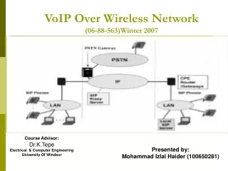
VoIP over Wireless
VoIP over Wireless. Phil Fleming Network Advanced Technology Group Network Business Motorola, Inc. Acknowledgements:. Material on PTT over GPRS provided by John Harris and Pranav Joshi in the Network Advanced Technology Group at Motorola, Inc

VoIP over Wireless
E N D
Presentation Transcript
VoIP over Wireless Phil Fleming Network Advanced Technology Group Network Business Motorola, Inc.
Acknowledgements: Material on PTT over GPRS provided by John Harris and Pranav Joshi in the Network Advanced Technology Group at Motorola, Inc Material on VoIP over Broadband Wireless provided by Amitava Ghosh and members of his team in the Network Advanced Technology Group at Motorola, Inc • Fan Wang • Wiemin Xiao
Outline • Push to talk over GPRS • Description • GPRS simulator • Performance results • VoIP over Broadband Wireless • History and evolution of broadband wireless • Voice path delay and user satisfaction • VoIP over HRPD-A (EV-DO-A) • Why it is going to happen • Voice path delay results from simulation • VoIP over HSDPA/HSUPA • VoIP over 802.16e
PTT over GPRS- Simulation Modeling and Analysis Pranav Joshi John Harris Motorola Inc., Networks Business
Overview: Push to Talk (PTT) • PTT over GPRS • service has been available for over a year • it is the first true commercial VoIP over cellular service. • Walkie-talkie-type service • focus on person-to-person rather than group call • Simulator – GENeSyS • Performance Results
Push-to-Talk between Alice and Bob • Alice (Originator) • Pushes the PTT button to talk with Bob • Waits for TPT (Talk-Permit-Tone) • Continues to hold button while speaking, • Releases when she is done • Bob (Target) • Audio from Alice plays out • TPT “beep” indicates Alice has released her PTT button • Pushes the button and waits for TPT • Continues to hold button until he is done speaking • Single user can transmit at given time (half-duplex channel) • Mobile plays “Bonk” if • User is not available • Any other user is speaking • Group Call: three or more users on single PTT call
PTT over GPRS, initial call setup Talk Proceed Tone Alice Presses PTT Alice Presses PTT 1st PTT setup delay UL TBF Setup UL TBF Setup UL Trans- UL Trans- mission DL TBF Setup DL TBF Setup DL Trans- mission DL Trans- mission Alice Alice Infrastructure Incl paging delay DL TBF Setup DL TBF Setup DL Trans- mission DL Trans- mission UL TBF Setup UL TBF Setup UL Trans- mission UL Trans- mission Bob Bob : MS processing & packet Assembly : MS processing
PTT over GPRS, subsequent PTT Talk Proceed Tone Bob Presses PTT : MS processing & packet assembly Subsequent Push timeline Bob UL TBF Setup UL Trans- mission DL TBF Setup DL Trans- mission EtoE Packet delay EtoE Packet delay Server processing Infrastructure Server keeps state information, i.e is aware of Alice’s situation Alice Response time
Performance and Capacity • User experience metrics • initial call setup delay • subsequent PTT delay • mouth-to-ear audio delay • audio turn around time – time from when Alice stops talking until she hears Bobs response playing out. • Service Provider Business Metrics • erlangs - average number of subscribers supported at sufficient user experience per • RF carrier • network element • system • system resources used per call
Features of the GENeSyS System Simulator • C, C++ • Discrete time simulator • Basic time unit of 20ms (one block period) • 8 timeslots per carrier • Simulator has: • Detailed modeling of RLC/MAC • Air Interface (RF) • Various traffic profiles • Simplified version of Core Network • Multi-carrier, multi-cell, various reuse patterns etc
0 GPRS Adaptive Coding SchemesThroughput per slot vs C/I 20 18 16 14 12 Throughput (kbps) 10 8 CS1 6 CS2 System planning for GSM voice 4 CS3 CS4 2 0 1 2 3 4 5 6 7 8 9 10 11 12 13 14 15 16 17 18 19 20 21 22 23 24 25 C/I
Simulation Configuration • 4.75 kbps vocoder with 20 msec. framing • 95 bits every 20 msec. when the user is speaking • 6 frames per IP packet • 43 bytes of overhead per IP packet • uncompressed IP header • Overall audio bit stream of 7.6 kbps • 6*95 + 43*8 = 570 + 344 = 914 bits per IP packet • 914 * 50 / 6 = 7616.7 bits per second • One PTT talk spurt ~ 5 sec of Audio • RLC Acknowledge Mode • radio frame (20 msec.) re-transmission protocol
Impact of Increasing Number of Dedicated Slots1 Uplink timeslot mode, coding scheme 1-2, dedicated timeslot 1 to 6 • Trunking benefit similar to that of Erlang-B formula observed: • Doubling the number of dedicated slots more than doubles the PTT capacity. • For example, increasing number of dedicated slots from three, up to six, increases the capacity by 3.1x • Capacities quoted correspond to knee of delay versus load curve
Impact of mobile station capability 1 Uplink timeslot mode Vs. 2 Uplink timeslot mode • Increasing the number of uplink timeslots the mobile is capable of from 1 2 significantly improves performance: • Audio delay • 1 UL timeslot: Light load ~2.0 sec and typical load ~2.4 sec • 2 UL timeslot: Light load ~1.6 sec and typical load ~2.1 sec • This benefit results from better fractional timeslot utilization with the improved mobile station capability – see next slide for visualization
Impact of mobile station capability 1 Uplink timeslot mode Vs. 2 Uplink timeslot mode • This benefit results from better fractional timeslot utilization with the improved mobile station capability • Consider a system with 2 dedicated non–hopped slots, & three CS2 mobiles • If 1 slot uplink capable • Capacity = 2 PTTs or 1/TS • If 2 slot uplink capable • Capacity = 3 PTTs Slot 1 Slot 2 MS1 MS2 ~12 Kbps ~12 Kbps Slot 1 Slot 2 MS1 MS2 MS3 ~12 Kbps ~12 Kbps
Impact of CS3/4 • CS 3-4 • Higher Throughput • Higher BLER or FER • High load Lower delay • Light load Higher delay due to additional re-tx
Changing Vocoder and Packetization • Vocoder & Packetization (scenarios) • 4.75 kbps, 6 frames/IP packet, service bit rate 7.6 kbps • 5.15 kbps, 10 frames/IP packet, service bit rate 6.9 kbps • Scenarios 2 has lower service bit rate over scenario 1 • Scenario 2 accumulated lower delay especially at high load
Performance Impact Study • Capacity improvement as numbers of dedicated slots increase • Delay and capacity benefit with 2 uplink timeslot mode • Effect on delay and capacity as we add coding scheme 3 & 4 capable system • Trunking efficiency improvement with switchable timeslots • Impact of vocoded frames per IP packets with different vocoder rate
VoIP over Broadband Wireless Phil Fleming Network Advanced Technology Group Motorola, Inc.
Performance Analysis Summary • mix: Ped A/B, Veh A 3 km/h • *DO-A results assume mobile diversity; Additional capacity in the FL w/ MAC mux • 2-frame bundling = Encapsulation of 2 EVRC frames into 1 RTP/UDP/IP packets
Internet Interface to the Public Network Base Site Controller Packet Core Packet Core Access Node MGX 8800 MGX 8800 Client Base Site (Access Point)
HRPD Channel Structure DRC.Lock
Forward Channel Structure • HRPD-0 Forward Channel Fundamentals • Time multiplexed channels • Pilot • initial acquisition, phase & timing recovery, channel estimation & combining, • means for predicting received C/I for setting DRC (data rate control), • MAC – three sub-channels (all users’ RPC+DRCLock CDMed along with RA) • Reverse Power Control (users RPC CDMed using MACIndex – size 64 Walsh) • RPC data rate = 600*(1- 1/DRCLockPeriod) bps • Reverse Activity (RA) one reverse link bit (RAB) per slot (MACIndex=4) • combined busy bit (CBB) is set to 1 if any sector sets RAB=1 else CBB=0 • CBB & Reverse link persistence value used by AT to determine max uplink rate allowed • DRCLock AN admission control – when asserted AT to stop selecting sector • Traffic (Forward Traffic Channel or FTC) • PHY Packet based variable rate traffic channel, data rates 38.4 Kbps to 2.4576 Mbps • QPSK, 8-PSK, and 16-QAM modulation ---- R=1/5, 1/3 Turbo Codes • PHY Packet sizes: QPSK: 1024 & 2048 bits, 8PSK: 3072 bits, 16QAM: 4096 bits • Frame length from 1 to 16 slots, slot length = 1.67ms • Control • Combines functions of IS-95 sync & paging channels w. rates of 38.4 & 76.8 Kbps • Transmitted 8 out of every 256 slots.
Forward Channel Structure • No power control: full cell power when transmitting. • Time division nature of the burst versus code division for cdma2000-1x • Scheduling done at access point (base station) • Multi-user diversity benefit • Provision for receive diversity (two antennas) at Access Terminal
Forward Channel Structure • Transmit slots use a 4-slot interlacing technique. Subsequent transmissions occur until decoding successful or maximum allowed re-transmissions. • Data sent @153.6 kbps is sent in four slots and repeated the following four slots • Maximum # of re-transmissions is dependent on the data rate selected. • Users can be scheduled for consecutive slots. Users can be scheduled for consecutive slots
Slot Structure of Forward Channel • No data transmissions occur at the same time as pilot (TDM) • High SNR for pilot signal resulting in accurate channel estimates
HRPD-0 Reverse Link • Similar to IS-2000-1x with the addition of the following channels • Reverse Rate Indicator (RRI) Channel --MAC-- • Indicate whether data channel is being transmitted or not & its corresponding rate • Data Rate Control (DRC) Channel --MAC-- • Indicate supportable forward traffic channel data rate • Best serving sector on the forward channel • Acknowledgement (ACK) Channel • The data packet transmitted on the forward traffic received successfully? (600Hz rate) • Parameters for Reverse Link • Traffic Channel Data Rate Support -- 9.6, 19.2, 38.4, 76.8 and 153.6 Kbps • HPSK (variation of BPSK modulation with better peak to average) • Packet duration of 26.67 msec (fixed frame length), 16 slots of 1.67msec • R=1/2 and R=1/4 Turbo encoder • CDM & SHO supported for reverse link traffic channels (not fast cell sel.) • Fast reverse power control supported (600*(1- 1/DRCLockPeriod) bps)
Physical Layer Enhancements in HRPD-A • Reverse Link Enhancements • Higher data rates and finer quantization • Support of data rates ranging from 4.8 kbps to 1.8 Mbps with 48 payload sizes • 4 slot sub-packets (6.66 ms) • Hybrid ARQ using fast re-transmission (re-tx) and early termination • Support of QPSK and 8-PSK modulation • Flexible rate allocation at each AT via autonomous as well as scheduled mode • 3-channel synchronous stop-and-wait protocol • Forward Link Enhancements • Peak rates increased from 2.4 Mbps to 3.1 Mbps • Additional small payload sizes (128, 256, 512 bits) • Improves frame fill efficiency • Data Source Control (DSC) Channel introduced (on RL) to indicate the desired forward-link serving cell • Minimize service interruption due to server switching on FL • Multi-user packet support
System Simulation Assumption: Forward Link • VoIP-only and mixture of VoIP and web browsing are modeled. • Voice traffic modeled by 4 state Markov chain. • 1/8th rate frames are blanked and not blanked • Vocoder frame bundling (multiple voice frames per IP packet) • 2-frame bundling and no-bundling • Overhead used in the simulation • 3 bytes RTP/UDP/IP, 5 bytes for PPP, and 3 bytes for RLP (11 bytes) • 6 bytes overhead (PPP header elimination) • Hybrid-ARQ included • Channel model: • 34/33/33% Ped-A/Ped-B/Veh-A • Scheduler • Proportional fair scheduler with delay multiplier. • Delay multiplier is a function of delay constraint. • Multi-user MAC multiplexing included ( up to 8 users) • AT Receive diversity • 2 way • Advanced Receiver • Have capability, not currently used
System Simulation Assumption : Reverse Link • VoIP-only • Voice traffic modeled by 4 state Markov chain. • 1/8th rate frames are blanked and not blanked • Vocoder frame bundling • 2-frame bundling and no-frame bundling • Overhead • 3 bytes RTP/UDP/IP, 5 bytes for PPP, and 3 bytes for RLP (11 bytes) • Also modeled a total of 6 bytes overhead • HARQ included • Channel model: • 34/33/33% Ped-A/Ped-B/Veh-A • Scheduler • Rate control scheduling • Reverse link overhead • DRC and Pilot channel (DRC to Pilot power ratio is set to –6 dB for repetition 8) • Ack/Nack channel (Ack/Nack to Pilot power ratio is set to 4 dB) • BTS Rx Diversity • 2-way • Interference Canceller at the BTS • Not included
Reverse Link Delay:2 Frame Bundling, Ped-A+Ped-B+Veh-A, RF Delay only (Maximum allowable pathloss = 130 dB) 40 Erl • 40 users can be supported with RF delay of 50 ms with 11 byte overhead • Users out of range are assumed dropped.
Reverse Link Delay:2 Frame Bundling, Ped-A+Ped-B+Veh-A, RF Delay only (Max allowable pathloss = 160dB) • 40 users can be supported with RF delay of 50 ms with 11 byte overhead • No restriction on location of users • Capacity drops by 5 Erlangs when the restriction is removed
Reverse Link Delay:No Frame Bundling, Ped-A+Ped-B+Veh-A, RF Delay only (Maximum allowable pathloss = 160 dB) • 40 users can be supported with RF delay of 50 ms with 11 byte overhead and no-frame bundling
Reverse Link Delay: 6 bytes overhead, Ped-A+Ped-B+Veh-A, RF Delay only (Maximum allowable pathloss = 130 dB) • With a 40 ms delay bound the 2-frame bundling performs better than no-frame bundling • If the delay bound is increased to 50 ms the performance with no frame and 2-frame bundling are identical (need some explanation)
Reverse Link Delay:6 bytes overhead, Ped A+Ped-B+Veh-A, 1/8 rate frames included • Capacity drops from 45 to 40 Erlangs if 1/8 rate frame is included with a RF delay of 50 ms • Complete blanking of 1/8th rate frames causes poor voice quality at the beginning of a talk spurt • Loss in performance not as significant as in forward link
Forward Link Delay: 2 Frame Bundling, Ped A+Ped-B+Veh-A, RF Delay only, w/ MAC Mux • MAC multiplexing of up to 8 users • 40 Erlangs can be supported with RF delay of 40 ms • Significant increase in capacity with MAC multiplexing
Forward Link Delay:6 bytes overhead, Ped A+Ped-B+Veh-A, 1/8 rate frames suppression, w/ MAC Mux • 40-45 Erlangs can be supported with RF delay of approximately 50 ms
Forward Link Delay:6 bytes overhead, Ped A+Ped-B+Veh-A, 1/8 rate frames included, w/ MAC Mux • Capacity drops from 45 to 30 Erlangs if 1/8 rate frame is included with a RF delay of 50 ms • Blanking of 1/8th rate frame results in a drop in voice quality at the beginning of a talk spurt
VoIP over HRPD-A Capacity: Conclusions • VoIP only capacity is balanced between forward and reverse links • 40-45 VoIP (Mobile to Mobile) Erlangs with a mixture of channels and 2 frame bundling with Mobile to Mobile delay of less than 250 ms • Two frame bundling has slightly greater capacity to no-frame bundling • Inclusion of 1/8th rate frames significantly degrades VoIP Capacity • Need to study the effect on MOS with various 1/8th rate frame blanking schemes • Trade-off between capacity and quality • Two frame or no frame bundling is the desired mode of operation since gaps in speech will lead to inferior voice quality with loss of packets with frame bundling greater than 2. • Mixture of VoIP and Web services can be supported. • Graceful degradation in data capacity as VoIP users are increased • ~250 kbps of FL data traffic with 25 Erlangs in both directions • Mobile diversity brings extra FL data throughput • Advance receiver at the MS will further increase FL throughput • Work in progress includes • Performance with both advanced receiver and RX diversity enabled in FL • Performance with 4-way RX diversity at BTS • Performance of RL with Interference Canceller
HSDPA Background • High Speed Downlink Packet Access • 3G (WCDMA Rel-99 & CDMA2000-1x Rel-C ) spectral efficiency ~ 2.5G (GSM/GPRS) for wireless packet data • SE significantly increased with technology enablers: • Fast distributed scheduling (at Node-B) • Fast AMC: H-ARQ + IR, higher-order modulation (ala EDGE), multi-code tx, smaller frame sizes, fast channel quality feedback. • HSDPA (Rel-5 WCDMA) is the evolution of WCDMA Rel-99/4 using technology enablers • 2ms sub-frames (vs 10ms frames), Peak Rate 14Mb/s • QPSK, 16QAM w. Stop&Wait H-ARQ and IR • Fast scheduling, Fast Ack/Nack & ch. quality feedback
HS-PDSCH Physical Channel • HS-PDSCH Physical Channel Fundamentals • Partitioned into static 2ms (3 timeslot) periods or “sub-frames” (2560 chips) • i.e. HSDPA Transmission Time Interval (TTI) is 2ms sub-frame • 5 sub-frames per 10ms frame • QPSK and 16-QAM modulation • Fixed length-16 symbol spreading • Code division multiplexing (CDM) of users per TTI
HSUPA Concept lower delay & higher capacity • High Speed Uplink Packet Access • E-DCH – enhanced uplink dedicated channel • Fast Node-B scheduling with HARQ and IR • control & minimize Rise over Thermal (RoT) variation • avoid RLC re-transmission delay and benefit from previous tx energy • #UEs per TTI depends on assignment of available RoT margin (left over R99/4/5) • Higher Rates • BPSK or QPSK modulation • Variable length (64 to 2) symbol spreading