Download
1 / 61
1.66k likes | 6.89k Vues
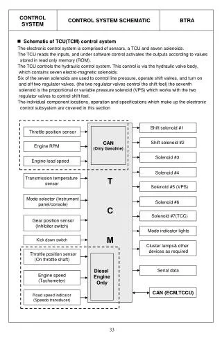
Train Control , Signalling & Telecommunication System for Delhi Metro. Delhi Metro Rail Corporation Ltd. DMRC came into existence in 1995 Phase I implementation period cut down from 10 years to 7 years Work on phase I started in 1998

E N D
Train Control , Signalling & Telecommunication System for Delhi Metro
Delhi Metro Rail Corporation Ltd. • DMRC came into existence in 1995 • Phase I implementation period cut down from 10 years to 7 years • Work on phase I started in 1998 • First section of about 8.5 km between Shahdara and Tis Hazari was opened by our Prime Minister on 24th Dec 2002
Delhi Metro Network – Phase I • Line 1 (Rail Corridor), 22 Km in Length • Elevated/ Surface • Shahdara – Rithala • R1 Section – Shahdara – Tis Hazari • R2 Section – Tis Hazari – Tri Nagar • R3 Section – Tri Nagar – Rithala • Line 2 (Metro Corridor), 11 Km in Length • Underground • Vishava Vidayalaya – Central Secretariat • M1 Section – Vishava Vidayalaya – Kashmere Gate • M2 Section – Kashmere Gate – Central Secretariat
Delhi Metro Network – Phase I (cont..) • Line 3 (East – West Corridor) • Mostly Elevated • 23 Km in Length • Barakhamba Road – Dwarka • Recently approved by GOM • S&T Contract yet to be finalized
Salient Features of the System for Line 1 and 2 • 25 kV AC Traction • Light-weight modern coaches • 60 kg Rail and Thick Web Switches • Bi-directional Running possible • Distance to Target based Automatic Train Protection System with Cab Signalling; Fixed Signals for Back Up • Centralised control from Operational Control Centre • System Designed for 8 Coach trains. Initially, only 4 coach trains
Planned Headway • Line 1(Rail Corridor): Design Headway of 120 seconds for sustained operating headway of 180 seconds • Line 2(Metro Corridor): Design Headway of 90 seconds for sustained operating headway of 120 seconds
Signalling System Overview • Computer Based Interlocking • Continuous Automatic Train Control • Automatic Train Protection (ATP) • Distance to Go with Track to Train communication through Coded AFTC with Cab Signalling • Automatic Train Supervision (ATS) • Automatic Route Setting; Automatic train Regulation • Centralized control from Operational Control Centre • Automatic Train Operation (ATO) • For Metro corridor only
Computer Based Interlocking • ALSTOM CBI – ASCV Smartlock® • Stations with points are called ‘Main’ or ‘CBI’ stations. All these stations have interlocking equipment (ASCV). Fixed Signals are provided at Entry & Exit to Interlocking • Stations without points are called ‘Secondary’ stations. These stations are controlled from ‘Main’ or ‘CBI’ stations. Normally, no fixed signals are provided at these stations • All interlocking are connected together through optical fibre link • Bi-directional Signalling. Main line is fully track circuited with Joint-less Coded AFTC called SDTC (Smartway Digital Track Circuit) or DIGICODE® • Non–Trailable ALSTOM MJ81 Point Machine on Main Line for operating 60 kg thick web switches
Automatic Train Protection (ATP) • Cab Signalling • Track Related Speed Profile generation based on line data and train data continuously along the track • Continuous monitoring of braking curve with respect to a defined target point • Monitoring of maximum permitted speed on the line and speed restrictions in force • Detection of over-speed with audio visual warning and application of brakes, if necessary • Maintaining safety distance between trains • Monitoring of stopping point • Monitoring of Direction of Travel and Rollback • Releasing doors on the correct side of the platform when train comes to a stop
Modes of Train Running • ATO or Auto • Only on Metro Corridor • ATP or SM (Supervised Manual) or MCS (Manual Cab Signal) • ROS (Running On Sight) • On failure of ATP mode • Max. Speed will be limited to 25 kmph by ATP • RM (Restricted Manual) • In Depot • Max. Speed will be limited to 25 kmph by ATP • Cut Out Mode • On complete failure of ATP Equipment • Max. Speed will be limited to 25 kmph by Rolling Stock
Movement of Trains in ATP Safety Margin
Fixed Signal Aspects and Indications • RED • Stop • VIOLET • Stop and Seek Instructions when working with fixed signals • Ignore when in Cab Signalled Mode • GREEN • Proceed when working with fixed signals • Ignore when in Cab Signalled Mode
Automatic Train Supervision(ATS) • Automatic Route setting • Automatic Train Regulation • Continuous Tracking of train position • Mimic Panel & Workstation interface • Adjustment of station dwell time • Link to Passenger Information Display System for online information • Computation of train schedules & Time table
Operation Control Center (OCC) • Located at Shastri Park • Will control both Rail & Metro Corridor • Domino Type Mimic Panel • SCADA for communication, Traction , Air conditioning, Ventilation and other Auxiliary Systems • ATS, Radio, SCADA,PIDS workstations for Traffic and other controllers
Automatic Train Operation (ATO) • Automatic control of Train running from station to station while remaining within the safety envelope of ATP • Opening of Train doors in the stations • Control of dwell time and performance in accordance with the headway/ timetable in conjunction with ATP/ ATS
First Section (Shahdara – Tis Hazari) Opened in December 2002 • R1–SR (R1-Speed Restriction) • No Cab Signalling at this stage. Trains run on fixed signals only • All six stations (including secondary stations) have Entry – Exit signals • Maximum permitted speed on the section is limited to 50 kmph • ATP provides only over-speed protection by application of Emergency Brakes
R1–SR (cont..) • Route Signals (Controlling Points) • Route not set or locked, Or first TC not clear: RED • Route set and locked, only first TC clear: VIOLET • Route set and locked, TCs ahead clear up to next signal + adequate distance: GREEN • Block Signals (No Points Ahead) • First TC not clear: RED • First TC clear: VIOLET • TCs ahead clear up to next signal + adequate distance (Buffer Block): GREEN • RED,VIOLET– Stop;GREEN– Proceed
Main Stages of Commissioning of Rail and Metro Corridor • R1 (Shahdara–Tis Hazari, 8.5km) • R1-SR (Dec 2002) • R1-SR with Local ATS (July 2003) • R1-R2 Combined (Shahdara–Tri Nagar, 13km) • Mastria ATP (Sept 2003) • ATP with Screen based MMI (Feb 2004) • R3, M1, M2 – Planned with full system
TELECOMMUNICATION IN DMRC • For efficient Management and operation, it is essential to have a well organised telecommunication network covering strategic locations like OCC, stations, depots and it is equally essential to have a relaible links between strategic locations and moving trains or working staff along the railway track • The telecommunication system provides all necessary communication channels for carrying voice , data and video signals for metro management and operation. • Telecommunication channels are used for telephone sub system and more than that for the control and supervision of the train from OCC,supervision of AFC and other data communication for DMRTS.
TELECOMMUNICATIONS IN DMRC FIBRE OPTICS SYSTEM INCLUDING MASTER CLOCK, NP-SCADA. RADIO SYSTEM TELEPHONE SYSTEM CCTV SYSTEM PA SYSTEM PIDS SYSTEM
FIBRE OPTIC TRANSMISSION SYSTEM The fibre optic transmission system provides a common transmission backbone for the subsystems . The FOTS have sufficient transmission bandwidth to cater for current operational needs of the Metro and Rail corridors as well as for future system expansion. The FOTS is equipped with a network management system to provide status monitoring, configuration , analysis and control of various network elements.
FIBRE OPTIC TRANSMISSION SYSTEM • Master clock system is equipped to provide the master clock sources for network synchronization and reference timing signal distribution for other sub system, designated systems and all slave clocks at stations , depots, OCC and DMRTS HQ. • A communication system supervisor including NP-SCADA shall monitor the status of the telecommunication equipment and ECS, Tunnel Ventilation , LV circuits etc as a whole.
FIBRE OPTIC TRANSMISSION SYSTEM SDH NETWORK SDH Nodes are provided at each station and depots. These SDH nodes consist of STM multiplexers with OLT connected to optical fibre cable backbone network to form the SDH network of the FOTS. The SDH network provides dual and self-healing protected transmission path. Each SDH node is of at least STM-4 level SDH nodes at OCC and at ISBT both for metro and Rail corridor shall be cross connect types and SDH nodes at other stations are add/drop multiplexers
NP-SCADA • NP-SCADA monitors various equipments of Rail and Metro corridor. • Provides data/information to maintenance staff to access the need for unscheduled preventive maintenance. • In addition to above facilitates, recording ,analysis and printing of data for effective maintenance.
RAIL CORRIDOR: Rail Temperature at selected location. FOR METRO CORRIDOR Fire Detection and Suppression System Lifts and Escalators Pumps Environment Control System Seismic Activity System Intrusion alarms Tunnel Ventilation System Equipment to be monitored through NMS at OCC or directly Master Clock System Fibre Optic Transmission System Telephone System Radio System Public Address System Passenger information and Display System Closed Circuit TV System UPS System VARIOUS SYSTEMS MONITORED BY NP-SCADA
MASTER CLOCK SYSTEM • Master clock is provided to assure uniform and reliable time information. • A GPS Master clock distributes correct time to Master clocks and other systems requiring correct time. • The Master clock is provided in OCC and transmits the correct time to the Sub-Master Clocks via LANs. • One Sub-Master Clock is placed in every station.
RADIO SYSTEM The Radio system shall comprise the following main functional elements • Train Radio to OCC and vice versa • Hand portable to OCC and vice versa • Hand portable to DCC and vice versa • SCR to OCC and Handportable/Train mobiles and vice versa. • Distress call between the train –borne mobile and hand portable as well as between hand portables.
RADIO SYSTEM • The Radio system is a digital trunked radio system operating in 380-400 Mhz band and confirming to TETRA standards. • The Radio system have central control equipment installed in OCC • Base station are installed at Welcome,Pulbangash, Rohini East for Rail corridor and at Connaught Place and ISBT for Metro corridor. • The audio and data is conveyed to the central equipment through FOTS. • The Radio system in MC have a leaky coaxial cable along each track in the tunnels for communication with train borne mobile radio.
RADIO SYSTEM Following categories of call are capable in radio system : Individual call-Point to Point voice calls. Group Call- communication between the number of users within a pre defined area. Broadcast call- One way call from OCC/DCC to all users of the same call group within a pre defined area. Data call- Text messages from train radio,hand portable or from OCC. Emergency call – Train and shunting emergency calls to designated controller. Direct Mode call – Voice calls possible both ways between train mobile and another train mobile,train borne mobile and hand portable and between hand portables located within a radius of 2 Km. Train PA call – OCC to train borne PA system.
TELEPHONE SYSTEM • The telephone system provides a digital EPABX fixed telephone network • The Telephone system includes a direct line telephone communication system to provide direct line telephone lines for train operation, traction power supply control and maintenance telephone lines for track , rolling stock , signalling and telecommunication . The system ensures instant , un interruptible communication between key location of DMRTS. • The EPABX network and direct line telephone communication system is equipped with a common network management system to provide user data management, alarm monitoring , performance monitoring and system administration functions. • The telephone system is provided with emergency telephone from direct line telephone system at fixed location close to cross passages along the tunnels. This network of telephones shall be accessible from SCR and OCC.