Voice Networking
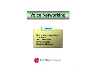
Voice Networking. Contents. What is Voice Networking ? LG Solution QSIG Connection VoIP Connection Networking Feature. Branch A. Head office. 400~450. Centralized Attendant. Branch B. ISDN IP network ATM, FR etc. 100~399. 500~599. Centralized Voice mail. Branch C.

Voice Networking
E N D
Presentation Transcript
Voice Networking Contents • What is Voice Networking ? • LG Solution • QSIG Connection • VoIP Connection • Networking Feature
Branch A Head office 400~450 Centralized Attendant Branch B • ISDN • IP network • ATM, FR etc 100~399 500~599 Centralized Voice mail Branch C 600~650 1. What is Voice Networking? Voice Networking Provides a way of communication to inter-work between networked system over various networks. • Headquarter to Branch offices • Chains • Office to Cargo • Building to Building 1/20
1. What is Voice Networking? Background • Offices are located everywhere. Should provide more efficiency for office worker. • Cost is growing and growing between Main and Branch offices. Benefit • Provide single network as one system • Cost effective with sharing the resources among multi-sites 2/20
1. What is Voice Networking? Protocols • DPNSS(Digital Private Network Signaling System) • QSIG of ETSI standards over ISDN • H.450 of ITU standards over VoIP • Proprietary protocols for enhanced feature by each vendor Remark1) RSG : Remote Service Gateway 3/20
IP Network 2. LG Solution Diagram RSG LDK-300E(CS-1000) DSL or Cable Modem Router Home Office BLF Manager Headquarter Office LDK-24 Small Branch Office LDK-100 Router LIK-300 Branch Office Router Local Main Office 4/20
2. LG Solution Flexibility to configure the systems • Up to 72 systems can be networked via public or private network. • Total solution from Home office to Headquarter office with LG Systems RSGrm1), LDK-24/100/300/300E, LIK-300 and CS-1000 Support Unified Numbering Plan • Allow uniform numbering plan for all users in the network. • The networked systems can be considered as one system. Therefore, extension in any system can talk with each other easily Remark1) RSG : Remote Service Gateway 5/20
2. LG Solution Support standard protocols • ETSI standards for QSIG interface over ISDN ETS 300-237 / 239 / 256 / 260 / 361 / 363 • ITU standards for H.450 interface over VoIP H.450.1 ~ H.450.9 • Proprietary protocol for enhanced features 6/20
2. LG Solution • Calling Line Identification (CLI) • Name Display • Net Basic Call • Call Transfer (Screened & Unscreened Transfer) • Call Forward (Unconditional / Busy / No Answer) • Call Offer (Camp-On) • Message Waiting Indication (MWI by Request) • Call Completion (Call Back) • Do Not Disturb (DND) • CO Transit-In/Out • Absent Text Message Service (LG Proprietary) • Centralized Attendant Service (LG Proprietary) • Centralized Voice Mail Service (LG Proprietary) • Busy Lamp Field (BLF) Service (LG Proprietary) • DECT Mobility (LG Proprietary) 7/20
3. QSIG Connection Direct Connection between Systems Master Slave PRIB MPB PRIB MPB STA NO 100 ~ 199 STA NO 200 ~ 299 NT mode TE mode LAN Minimum Requirements: 1. PRIB cards 2. QSIG Lock Key for each system Additional Requirements 1. LANU of MPB 2. PC for BLF Manager 3. HUB and IP Address for IP Connection BLF Manager 8/20
3. QSIG Connection Basic Programming Master System Slave System 1. Station range: 100~199 2. MPB IP Address: 192.168.23.10 3. CO Line type : Type 3(DID/MSN) 4. Networking Table PGM320 BTN 1 : Net Enable PGM321 BTN 4 (BLF MGR) : 192.168.23. 20 PGM322 (Net CO) BTN 1 : Net CO Group = 01 BTN 4 : Net CO Type = NET PGM324 BIN 00 (Master, itself) BTN 1 (Usage) = NET BTN 2 (STA Number) = 1#** BTN 3 (Net CO Gr) = 00 BIN 01 (Slave system) BTN 1 (Usage) = NET BTN 2 (STA Number) = 2** BTN 3 (Net CO Gr) = 01 BTN 4 (CPN) = Empty 1. Station range: 200~299 2. MPB IP Address: 192.168.23.11 3. CO Line type : Type 3(DID/MSN) 4. Networking Table PGM320 BTN 1 : Net Enable PGM321 BTN 4 (BLF MGR) : 192.168.23. 20 PGM322 (Net CO) BTN 1 : Net CO Group = 01 BTN 4 : Net CO Type = NET PGM324 BIN 00 (Slave, itself) BTN 1 (Usage) = NET BTN 2 (STA Number) = 2#** BTN 3 (Net CO Gr) = 00 BIN 01 (Master system) BTN 1 (Usage) = NET BTN 2 (STA Number) = 1** BTN 3 (Net CO Gr) = 01 BTN 4 (CPN) = Empty Station Number For BLF Service PRIB for Net Path PRIB for Net Path NET or PSTN Own STA number CO doesn’t need Net for Net Call PSTN for Transit Refer to PGM322 Direct connection Note: Each system in Networking range should have its corresponding programming like the above. 9/20
4. VoIP Connection VoIP Connection between Systems Master Slave VoIB MPB VoIB MPB STA NO 100 ~ 199 STA NO 200 ~ 299 LAN Minimum Requirements: 1. VoIB cards 2. IP Networking Lock Key for each system 3. HUB and IP Address for IP Connection Additional Requirements 1. LANU of MPB 2. PC for BLF Manager BLF Manager 10/20
4. VoIP Connection Basic Programming Master System Slave System 1. Station range: 100~199 2. MPB IP Address: 192.168.23.10 3. VoIB IP Address: 192.168.23.21 4. CO Line type : Type 3(DID/MSN) 5. Networking Table PGM320 BTN 1 : Net Enable PGM321 BTN 4 (BLF MGR) : 192.168.23. 20 PGM322 (Net CO) BTN 1 : Net CO Group = 01 BTN 4 : Net CO Type = NET PGM324 BIN 00 (Master, itself) BTN 1 (Usage) = NET BTN 2 (STA Number) = 1#** BTN 3 (Net CO Gr) = 00 BIN 01 (Slave system) BTN 1 (Usage) = NET BTN 2 (STA Number) = 2** BTN 3 (Net CO Gr) = 01 BTN 4 (CPN) = 192.168.23.22 1. Station range: 200~299 2. MPB IP Address: 192.168.23.11 3. VoIB IP Address: 192.168.23.22 4. CO Line type : Type 3(DID/MSN) 5. Networking Table PGM320 BTN 1 : Net Enable PGM321 BTN 4 (BLF MGR) : 192.168.23. 20 PGM322 (Net CO) BTN 1 : Net CO Group = 01 BTN 4 : Net CO Type = NET PGM324 BIN 00 (Slave, itself) BTN 1 (Usage) = NET BTN 2 (STA Number) = 2#** BTN 3 (Net CO Gr) = 00 BIN 01 (Master system) BTN 1 (Usage) = NET BTN 2 (STA Number) = 1** BTN 3 (Net CO Gr) = 01 BTN 4 (CPN) = 192.168.23.21 Station Number For BLF Service VoIP line for Net Path PRIB for Net Path NET or PSTN Own STA number CO doesn’t need Net for Net Call PSTN for Transit Refer to PGM322 IP address 11/20
5. Networking Feature Basic Call Step 8 100 101 Internet Step 5 102 Step 1 ~ 4 Call Flow Step Flow 1 Extension 101 dials 202 in Slave System Step 6 ~ 7 2 System searches Networking Numbering Table. 3 2** matches 202 4 System gets destination IP address (10.152.32.67 or 192.168.1.1) 5 VoIP call goes to destination IP 200 201 202 6 Ringing at the exact destination (202) 7 Destination (202) answers 8 Conversation Note:During conversation, all telephony features are available. For example, call transfer, hold, conference and etc. 12/20
Call Flow Step Flow 1 Outside Caller dials a station in master system 2 Call comes in master system 3 Extension 100 answers and converses 4 Extension 100 transfers the call to 202, and goes to Idle 5 Extension 202 rings and answers 6 Conversation 5. Networking Feature Transfer Call Step 1 ~ 2 PSTN or ISDN Step 6 Step 3 Internet 100 Step 4 Step 5 202 13/20
Call Flow Step Flow 1 Extension 100 set forward to 202 2 Outside Caller dials in Extension 100 3 Call is diverted to Extension 202 Extension 202 rings instead of 100 4 Conversation 5 5. Networking Feature Call Forward Step 2 PSTN or ISDN Step 5 Step 1 Internet 100 Step 3 Step 4 202 14/20
Call Flow Step Flow 1 Extension 100 dials 202, but hears BUSY tone 2 100 dials camp-on code “*” 3 Call is diverted to Extension 202 Extension 202 gets camp-on signaling 4 Conversation by pressing Hold button 5 5. Networking Feature Call Offer Step 1 Internet 100 Step 3 Step 2 Step 5 BUSY Step 4 202 15/20
Call Flow Step Flow 1 Extension 100 dials 202, but hears BUSY tone 2 Extension 100 press CALL_BK button, and goes to IDLE 3 Call-back ring to extension 100 when 202 is IDLE Extension 100 lifts handset, then extension 202 is ringing 4 Conversation 5 5. Networking Feature CCBS Step 1 Step 2 Internet 100 Step 4 Step 3 BUSY Step 5 202 16/20
Call Flow Step Flow 1 Extension 202 dials CO transit code of PGM 324 2 Dialed digit goes to master system Master seizes the real PX CO line and dials 3 Outside party rings 4 Conversation 5 5. Networking Feature Transit-Out Step 4 PSTN or ISDN Step 3 Step 5 Additional Programming Master : PGM 322 BTN 1 (Net Col Gr) = 02 for PSTN Lines BTN 4 (Net CO Type) = PSTN PGM 324 BIN 10 BTN 1 (Usage) = PSTN BTN 2 (Net Code) = 9 (transit code) Delete 1st CO Gr access code BTN 3 (Net CO Gr) = 02 Slave : PGM 324 BIN 10 BTN 1 (Usage) = PSTN BTN 2 (Net Code) = 9 (transit code) Delete 1st CO Gr access code BTN 3 (Net CO Gr) = 01 BTN 4 (CPN) = 192.168.23.21 BTN 7 (DGT Repeat) = YES Internet Step 2 Step 1 202 17/20
Call Flow Step Flow 1 Outside Caller dials a station in slave system 2 Call comes in master system and search FLEX DID table Master searches Flexible DID table 3 Call is diverted and ringing to EXT 202 4 Conversation 5 5. Networking Feature Transit-In Step 1 PSTN or ISDN Step 2 Step 5 Internet Step 3 Additional Programming Master : PGM 143 BTN 4 (DID Conv Type) = 2 PGM 231 (Flexible DID Table) = Assign Slave extension Step 4 202 18/20
Call Flow Step Flow 1 Extension 202 is BUSY 2 BLF information broadcasts to networked systems 5. Networking Feature BLF Service Internet 100 Step 2 BUSY Step 1 202 BLF Manager 19/20
Call Flow Step Flow 1 DECT user moves to another system 2 Call to the DECT user is routed to another system 5. Networking Feature DECT Mobility PSTN or ISDN Internet Additional Programming The WHTU should be registered both systems and the physical port number of WHTU should be same on whole systems. Master : PGM 324 BIN 01 BTN 6 (MPB IP Address) assign MPB IP address of slave Slave : PGM 324 BIN 01 BTN 6 (MPB IP Address) assign MPB IP address of master 20/20