Download
1 / 12
120 likes | 257 Vues
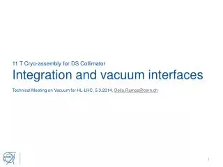
11 T Cryo-assembly for DS Collimator Integration and vacuum interfaces. Technical Meeting on Vacuum for HL-LHC, 5.3.2014, Delio.Ramos@cern.ch. Cryostat and collimator integration concept. MB. 15’660 between interconnect planes. Collimator.

E N D
11 T Cryo-assembly for DS CollimatorIntegration and vacuum interfaces Technical Meeting on Vacuum for HL-LHC, 5.3.2014, Delio.Ramos@cern.ch
Cryostat and collimator integration concept MB 15’660 between interconnect planes Collimator 11T Cryo-assembly for DS collimator Replace one LHC dipole with two 11 T magnets plus one collimator
Cryostat and collimator integration concept 15’660 between interconnect planes Possible additional splices Straight transfer line X Collimator independently supported to the floor Cold mass A Cold mass B Collimator Reinforced jacks to widstand vacuum forces Busbar splice and interconnect done in the tunnel Transfer lines lines M, E, N, K, C’ Busbar lyra 11T Cryo-assembly for DS collimator
Main features 11T Cryo-assembly for DS collimator • Two indenpendently assembled, transported and installed cryo assemblies • Expansion joints on transfer lines for alignment flexibility and thermal contraction • Interfaces to adjacent magnets remain standard • Splice and piping interconnect in the tunnel, prior to collimator installation • Rom temperature collimator independently supported to the floor • Mechanical decoupling of collimator from cryostats • Sectorised vacuum baked system • One collimator design fits beam 1 and beam 2 • Profits from existing TCLD design
Access for in-situ repair Cold mass A Cold mass B Collimator 11T Cryo-assembly for DS collimator Once the collimator removed, the vacuum vessel cover can slide open (welded joints designed for cut and re-welding) In-situ access for repair of “fragile” components: Expansion joints, Flexible hoses, Diode (tbc), Instrumentation feedthrough (IFS), Trim current leads (tbc), etc
Conceptual 3D integration 11T Cryo-assembly for DS collimator
Cold beam vacuum Special termination avoided with 50/53 cold bore Beam screen bellows Plugin module Sector valve Drift tube 11 T cold mass Collimator Bellows Port for RF ball test Cold to warm transition • Standard 50/53 mm cold bore and beam screens • Magnet bore 60 mm (MB is 56 mm): annular He volume for improved cooling • Aperture to be confirmed by on‐going beam dynamics studies • No changes to adjacent magnets • Cold to warm transition • Based on Q1 design for minimised length • External port for RF-ball test • Standard assembly procedure
Will it fit in 15660 mm? (Lengths for collimator beam line) Shortened to 800 mm Estimated potential for optimisation Important contribution from TE-VSC
Today’s main integration topics 11T Cryo-assembly for DS collimator
Before the 11 T magnet development: QTC (2010) 4.0 m + 0.5 m interc. = 4.5 m installation length Main drawback: extensive machine layout changes to create space
Could the QTC cryostat concept be “extended”? Cover closure w/ fillet welds New approach needed Longitudinal butt-welds • Can only be finished after cryostating • Dealing with welding distortions is a major issue • Distortions amplified with length • Adjustment of cold support posts is required • Complicated assembly procedure