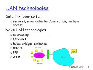
LAN Technologies
LAN Technologies. Completing Lecture 2. Ethernet Technologies: 10Base2. 10: 10Mbps; 2: under 200 meters max cable length thin coaxial cable in a bus topology repeaters used to connect up to multiple segments

LAN Technologies
E N D
Presentation Transcript
LAN Technologies Completing Lecture 2 Lecture 3
Ethernet Technologies: 10Base2 • 10: 10Mbps; 2: under 200 meters max cable length • thin coaxial cable in a bus topology • repeaters used to connect up to multiple segments • repeater repeats bits it hears on one interface to its other interfaces: physical layer device only! Lecture 3
10BaseT and 100BaseT • 10/100 Mbps rate; latter called “fast ethernet” • T stands for Twisted Pair • Hub to which nodes are connected by twisted pair, thus “star topology” • CSMA/CD implemented at hub Lecture 3
10BaseT and 100BaseT (more) • Max distance from node to Hub is 100 meters • Hub can disconnect “jabbering” adapter • Hub can gather monitoring information, statistics for display to LAN administrators Lecture 3
Gbit Ethernet • use standard Ethernet frame format • allows for point-to-point links and shared broadcast channels • in shared mode, CSMA/CD is used; short distances between nodes to be efficient • uses hubs, called here “Buffered Distributors” • Full-Duplex at 1 Gbps for point-to-point links Lecture 3
Hubs, Bridges and Switches Lecture 3 Lecture 3
Interconnecting LANs Q: Why not just one big LAN? • Limited amount of supportable traffic: on single LAN, all stations must share bandwidth • limited length: 802.3 (Ethernet) specifies maximum cable length • large “collision domain” (can collide with many stations) • limited number of stations: 802.5 (token ring) have token passing delays at each station Lecture 3
Hubs • Physical Layer devices: essentially repeaters operating at bit levels: repeat received bits on one interface to all other interfaces • Hubs can be arranged in a hierarchy (or multi-tier design), with backbone hub at its top Lecture 3
Hubs (more) • Each connected LAN referred to as LAN segment • Hubs do not isolate collision domains: node may collide with any node residing at any segment in LAN • Hub Advantages: • simple, inexpensive device • Multi-tier provides graceful degradation: portions of the LAN continue to operate if one hub malfunctions • extends maximum distance between node pairs (100m per Hub) Lecture 3
Hub limitations • single collision domain results in no increase in max throughput • multi-tier throughput same as single segment throughput • individual LAN restrictions pose limits on number of nodes in same collision domain and on total allowed geographical coverage • cannot connect different Ethernet types (e.g., 10BaseT and 100baseT) Why? Lecture 3
Bridges • Link Layer devices: operate on Ethernet frames, examining frame header and selectively forwarding frame based on its destination • Bridge isolates collision domains since it buffers frames • When frame is to be forwarded on segment, bridge uses CSMA/CD to access segment and transmit Lecture 3
Bridges (more) • Bridge advantages: • Isolates collision domains resulting in higher total max throughput, and does not limit the number of nodes nor geographical coverage • Can connect different type Ethernet since it is a store and forward device • Transparent: no need for any change to hosts LAN adapters Lecture 3
Backbone Bridge Lecture 3
Interconnection Without Backbone • Not recommended for two reasons: - single point of failure at Computer Science hub - all traffic between EE and SE must path over CS segment Lecture 3
Bridges: frame filtering, forwarding • bridges filter packets • same-LAN -segment frames not forwarded onto other LAN segments • forwarding: • how to know on which LAN segment to forward frame? Lecture 3
Bridge Filtering • bridges learn which hosts can be reached through which interfaces: maintain filtering tables • when frame received, bridge “learns” location of sender: incoming LAN segment • records sender location in filtering table • filtering table entry: • (Node LAN Address, Bridge Interface, Time Stamp) • stale entries in Filtering Table dropped (TTL can be 60 minutes) Lecture 3
Bridge Operation • bridge procedure(in_MAC, in_port,out_MAC) lookup in filtering table (out_MAC) receive out_port if (out_port not valid) /* no entry found for destination*/ then flood; /* forward on all but the interface on which the frame arrived*/ if (in_port = out_port) /*destination is on LAN on which frame was received */ then drop the frame Otherwise (out_port is valid) /*entry found for destination*/ then forward the frame on interface indicated; Lecture 3
Bridge Learning: example Suppose C sends frame to D and D replies back with frame to C • C sends frame, bridge has no info about D, so floods to both LANs • bridge notes that C is on port 1 • frame ignored on upper LAN • frame received by D Lecture 3
Bridge Learning: example C 1 • D generates reply to C, sends • bridge sees frame from D • bridge notes that D is on interface 2 • bridge knows C on interface 1, so selectively forwards frame out via interface 1 Lecture 3
B 2 2 A , 1 A , 1 2 2 1 1 A What will happen with loops?Incorrect learning Lecture 3
What will happen with loops?Frame looping C 2 2 C,?? C,?? 1 1 A Lecture 3
What will happen with loops?Frame looping B 2 2 B,2 B,1 1 1 A Lecture 3
Introducing Spanning Tree • Allow a path between every LAN without causing loops (loop-free environment) • Bridges communicate with special configuration messages (BPDUs) • Standardized by IEEE 802.1D Note: redundant paths are good, active redundant paths are bad (they cause loops) Lecture 3
Spanning Tree Requirements • Each bridge is assigned a unique identifier • A broadcast address for bridges on a LAN • A unique port identifier for all ports on all bridges • MAC address • Bridge id + port number Lecture 3
Spanning Tree Concepts:Root Bridge • The bridge with the lowest bridge ID value is elected the rootbridge • One root bridge chosen among all bridges • Every other bridge calculates a path to the root bridge Lecture 3
Spanning Tree Concepts:Path Cost • A cost associated with each port on each bridge • default is 1 • The cost associated with transmission onto the LAN connected to the port • Can be manually or automatically assigned • Can be used to alter the path to the root bridge Lecture 3
Spanning Tree Concepts:Root Port • The port on each bridge that is on the path towards the root bridge • The root port is part of the lowest cost path towards the root bridge • If port costs are equal on a bridge, the port with the lowest ID becomes root port Lecture 3
Spanning Tree Concepts:Root Path Cost • The minimum cost path to the root bridge • The cost starts at the root bridge • Each bridge computes root path cost independently based on their view of the network Lecture 3
Spanning Tree Concepts: Designated Bridge • Only one bridge on a LAN at one time is chosen the designated bridge • This bridge provides the minimum cost path to the root bridge for the LAN • Only the designated bridge passes frames towards the root bridge Lecture 3
Example Spanning Tree B8 B3 B5 • Protocol operation: • Picks a root • For each LAN, picks a designated bridgethat is closest to the root. • All bridges on a LANsend packets towards the root via the designatedbridge. B7 B2 B1 B6 B4 Lecture 3
Example Spanning Tree B8 Spanning Tree: B3 B5 B1 root port B7 B2 B2 B4 B5 B7 B1 Root B8 Designated Bridge B6 B4 Lecture 3
Spanning Tree Algorithm:An Overview • 1. Determine the rootbridge among all bridges • 2. Each bridge determines its root port • The port in the direction of the root bridge • 3. Determine the designated bridge on each LAN • The bridge which accepts frames to forward towards the root bridge • The frames are sent on the root port of the designated bridge Lecture 3
Spanning Tree Algorithm:Selecting Root Bridge • Initially, each bridge considers itself to be the root bridge • Bridges send BDPU frames to its attached LANs • The bridge and port ID of the sending bridge • The bridge and port ID of the bridge the sending bridge considers root • The root path cost for the sending bridge • Best one wins • (lowest root ID/cost/priority) Lecture 3
Spanning Tree Algorithm:Selecting Root Ports • Each bridge selects one of its ports which has the minimal cost to the root bridge • In case of a tie, the lowest uplink (transmitter) bridge ID is used • In case of another tie, the lowest port ID is used Lecture 3
Spanning Tree Algorithm:Select Designated Bridges • Initially, each bridge considers itself to be the designated bridge • Bridges send BDPU frames to its attached LANs • The bridge and port ID of the sending bridge • The bridge and port ID of the bridge the sending bridge considers root • The root path cost for the sending bridge • 3. Best one wins • (lowest ID/cost/priority) Lecture 3
Forwarding/Blocking State • Root and designated bridges will forward frames to and from their attached LANs • All other ports are in the blocking state Lecture 3
Bridges vs. Routers • both store-and-forward devices • routers: network layer devices (examine network layer headers) • bridges are Link Layer devices • routers maintain routing tables, implement routing algorithms • bridges maintain filtering tables, implement filtering, learning and spanning tree algorithms Lecture 3
Routers vs. Bridges Bridges + and - + Bridge operation is simpler requiring less processing - Topologies are restricted with bridges: a spanning tree must be built to avoid cycles - Bridges do not offer protection from broadcast storms (endless broadcasting by a host will be forwarded by a bridge) Lecture 3
Routers vs. Bridges Routers + and - + arbitrary topologies can be supported, cycling is limited by TTL counters (and good routing protocols) + provide firewall protection against broadcast storms - require IP address configuration (not plug and play) - require higher processing • bridges do well in small (few hundred hosts) while routers used in large networks (thousands of hosts) Lecture 3
Ethernet Switches • layer 2 (frame) forwarding, filtering using LAN addresses • Switching: A-to-B and A’-to-B’ simultaneously, no collisions • large number of interfaces • often: individual hosts, star-connected into switch • Ethernet, but no collisions! Lecture 3
Ethernet Switches • cut-through switching: frame forwarded from input to output port without awaiting for assembly of entire frame • slight reduction in latency • combinations of shared/dedicated, 10/100/1000 Mbps interfaces Lecture 3
Ethernet Switches (more) Dedicated Shared Lecture 3
Optional: Wireless LAN and PPP Lecture 3
IEEE 802.11 Wireless LAN • wireless LANs: untethered (often mobile) networking • IEEE 802.11 standard: • MAC protocol • unlicensed frequency spectrum: 900Mhz, 2.4Ghz • Basic Service Set (BSS) (a.k.a. “cell”) contains: • wireless hosts • access point (AP): base station • BSS’s combined to form distribution system (DS) Lecture 3
Ad Hoc Networks • Ad hoc network: IEEE 802.11 stations can dynamically form network withoutAP • Applications: • “laptop” meeting in conference room, car • interconnection of “personal” devices • battlefield • IETF MANET (Mobile Ad hoc Networks) working group Lecture 3
IEEE 802.11 MAC Protocol: CSMA/CA 802.11 CSMA: sender - if sense channel idle for DISF sec. then transmit entire frame (no collision detection) -ifsense channel busy then binary backoff 802.11 CSMA receiver: if received OK return ACK after SIFS Lecture 3
IEEE 802.11 MAC Protocol 802.11 CSMA Protocol: others • NAV: Network Allocation Vector • 802.11 frame has transmission time field • others (hearing data) defer access for NAV time units Lecture 3
Hidden Terminal effect • hidden terminals: A, C cannot hear each other • obstacles, signal attenuation • collisions at B • goal: avoid collisions at B • CSMA/CA: CSMA with Collision Avoidance Lecture 3
Collision Avoidance: RTS-CTS exchange • CSMA/CA: explicit channel reservation • sender: send short RTS: request to send • receiver: reply with short CTS: clear to send • CTS reserves channel for sender, notifying (possibly hidden) stations • avoid hidden station collisions Lecture 3
Collision Avoidance: RTS-CTS exchange • RTS and CTS short: • collisions less likely, of shorter duration • end result similar to collision detection • IEEE 802.11 allows: • CSMA • CSMA/CA: reservations • polling from AP Lecture 3