Download

1 / 70
870 likes | 1.23k Vues
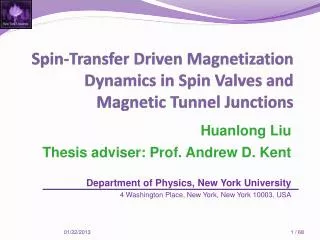
Spin-Transfer Driven Magnetization Dynamics in Spin Valves and Magnetic Tunnel Junctions. Huanlong Liu Thesis adviser: Prof. Andrew D. Kent Department of Physics, New York University 4 Washington Place, New York, New York 10003, USA. Introduction. Charge current. Spin current.

E N D
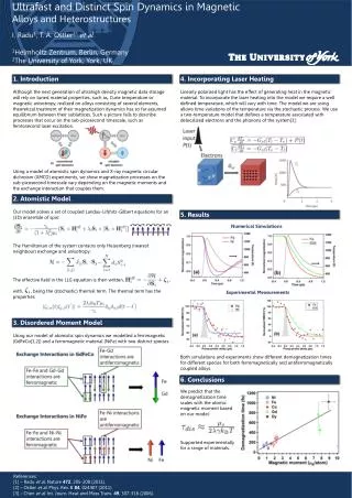
Spin-Transfer Driven Magnetization Dynamics in Spin Valves and Magnetic Tunnel Junctions Huanlong Liu Thesis adviser: Prof. Andrew D. Kent Department of Physics, New York University 4 Washington Place, New York, New York 10003, USA
Introduction Charge current Spin current Spintronics: utilize the electron spin and its associated magnetic moment. Physics: the interaction between the spins of itinerant electronsand the magnetizationof a ferromagnet.
GMR effects • Giant magnetoresistance (GMR): • Discovered (1988) • Albert Fert, the University of Paris-Sud, France, • Peter Grünberg, Forschungszentrum Jülich, Germany • Nobel Prize in Physics (2007) ferromagnet non-magnetic metal ferromagnet Resistance depends on the relative orientation of the two ferromagnetic layers R
Explanation – GMR Magnetization influences the spin of electrons Spin polarized Magnetoresistance ratio: typically a few percent or less
Spin Transfer Torque • J. C. Slonczewski (1996) Spins of the electrons can also influence the magnetization Spin transfer torque (STT) This thesis: Spin-transfer driven magnetization dynamics in magnetic nanopillars Angular momentum conservation spin-polarized current • Dimensions: tens/hundreds of nanometers in x and y, several nm in z (height) • Timescales: tens/hundreds of picoseconds (intrinsic timescale) to DC magnetization change with time
Applications in Spintronics – two out of many • Hard disks: • Magnetic Random Access Memory (MRAM): • non-volatile • low power consumption • high density • fast read/write time “A universal memory” in development
Outline – projects and collaborators Spin transfer switching and relaxation in all-perpendicular spin valves 1. Eric Fullerton Jordan Katine StéphaneMangin Jonathan Sun Huanlong Liu Daniel Bedau Andrew D. Kent Switching and precession in magnetic tunnel junction devices 2. Juergen Langer Jordan Katine Huanlong Liu Daniel Bedau Dirk Backes Andrew D. Kent
Spin transfer switching and relaxation in all-perpendicular spin valves D. Bedau, H. Liu, J. Z. Sun, J. A. Katine, E. E. Fullerton, S. Mangin, and A. D. Kent Appl. Phys. Lett.97, 262502 (2010) D. Bedau, H. Liu, J. J. Bouzaglou, A. D. Kent, J. Z. Sun, J. A. Katine, E. E. Fullerton, and S. ManginAppl. Phys. Lett. 96, 022514 (2010) H. Liu, D. Bedau, J. Z. Sun, S. Mangin, E. E. Fullerton, J. A. Katine, and A. D. Kent Phys. Rev. B85, 220405(R) (2012)
Introduction – spin transfer switchingand relaxation in all-perpendicular spin valves damping magnetizationrotation spin transfer torque Spin transfer torque (STT): Project 2: MTJs Project 1: all-perp. spin valves • J. C. Slonczewski (1996) Landau-Lifshitz-Gilbert (LLG) equation + STT: Intrinsic timescales: tens/hundreds of picoseconds
Introduction – spin transfer switching and relaxation in all-perpendicular spin valves • Two ferromagnetic layers separated by a non-magnetic metal layer • Free layer (FL): • Design to be switched • Two preferred directions • Reference layer (RL): • Magnetization remain fixed during FL switching • Generate spin-polarized current to switch the FL • Detect the FL direction through GMR • Non-magnetic metal layer: • Long spin diffusion length (SDL) • Cu: SLD ~ hundreds of nanometers at room temperature Project 2: MTJs Project 1: all-perp. spin valves
All-perpendicular spin valves • High energy barrier • Low critical current • High density • High symmetry Project 2: MTJs Project 1: all-perp. spin valves • First spin-transfer experiments in all-perpendicular device: Mangin et. al., Nat. Mater. 5, 210 (2006) • Only quasi-static measurements. Need faster experiments to probe the magnetization dynamics.
Sample structure • [Co/Ni] free layer (FL), 1.6 nm thick • [Co/Ni]|[Co/Pt] reference layer (RL) • high coercive field (> 0.5 T) • Measured > 20 samples • Present results on: • 100 nm x 100 nm • 50 nm x 50 nm samples Project 2: MTJs Project 1: all-perp. spin valves
Modeling Is there an analytic prediction for experiments?
A macrospin model minus damping Project 2: MTJs Project 1: all-perp. spin valves Current Pulse: In general, both STTand thermal fluctuations influence the switching process. • θ0: Initial magnetization angle when current pulse is applied, a distributed quantity whose probability is determined by the Boltzmann distribution. • θτ: Final magnetization angle when current pulse stops, determines whether or not a switching event would result.
STT Thermal fluctuations Initial state Final state Large current – short time limit: STT > Thermal fluctuations Small current – long time limit: STT < Thermal fluctuations Project 2: MTJs Project 1: all-perp. spin valves Pulse simplify simplify • Thermally distributed initial states and deterministic switching process (only STT). • Thermal activation over an energy barrier which is modified by STT. deterministic
Analytic solutions • Short time: • Linear boundary: • Long time: • Exponential boundary: Project 2: MTJs Project 1: all-perp. spin valves STT Current Pulse: damping Switching Probability:
Experiments on Switching How does the switching probability P depend on the pulse amplitude I and duration τ?
Measurement circuit Bias-tee: τ< 10 ns Switch: τ > 5 ns Project 2: MTJs Project 1: all-perp. spin valves μ0Happ top bottom top e- bottom sample
Experimental setup Project 2: MTJs Project 1: all-perp. spin valves
Switching at DC Project 2: MTJs Project 1: all-perp. spin valves Room temperature coercive field: 100 mT Hysteresis loop shift: 25 mT Switching currents: -7 mA, 4 mA P AP
Switching at DC Project 2: MTJs Project 1: all-perp. spin valves Room temperature coercive field: 90 mT Hysteresis loop shift: -40 mT Switching currents: 0.4 mA, -1 mA P AP
Switching at DC Project 2: MTJs Project 1: all-perp. spin valves • Ratio of size: 4 • Ratio of resistance: ~ 1 / 3 • Ratio of MR ~ 1 • Ratio of coercive field: ~ 1 • Ratio of critical current: ~ 8
Pulse measurements μ0Happ = 0.2 T 3 1 2 4 μ0Happ = 0 T Project 2: MTJs Project 1: all-perp. spin valves Apply measurement field and current Saturate Check if switched Apply pulse If switched go here If NOT switched go here Apply the same pulse 100 – 10,000 times
Pulse measurements Switching diagram Project 2: MTJs Project 1: all-perp. spin valves Duration scan Amplitude scan
50% switching boundary A: dynamic parameter, the slope. – Efficiency Ic: zero temperature critical current, the intercept at x-axis. – Threshold Project 2: MTJs Project 1: all-perp. spin valves Intrinsic damping Icτ Net charge (I – Ic)τ
50% switching boundary Project 2: MTJs Project 1: all-perp. spin valves
50% switching boundary Project 2: MTJs Project 1: all-perp. spin valves
Field dependence of A andIc Initial state Final state Project 2: MTJs Project 1: all-perp. spin valves Pulse • Possible reasons causing the discrepancy: • Switching process is not uniform • Thermal fluctuations influence the switching process as well
50% switching boundary Short time regime Project 2: MTJs Project 1: all-perp. spin valves Long time regime Cross over regime • Measure with pulse durations over 10 order of magnitude in time. • Model yields correct forms at both short and long time limits. • Three regimes can be distinguished.
Probability ~ pulse duration Project 2: MTJs Project 1: all-perp. spin valves short time regime: long time regime:
Probability ~ pulse amplitude Project 2: MTJs Project 1: all-perp. spin valves short time regime: long time regime:
Probability ~ angular momentum • Probability only depends on the net charge in short time regime • Angular momentum conservation • Refine short time regime net charge: Project 2: MTJs Project 1: all-perp. spin valves
tdelay I1 I2 I1 I2 Double Pulse Experiments t1 t2 Use the second pulse to probe the magnetization dynamics excited by the first pulse t1 t2 Difficulty: no electrical signal during relaxation Solution: a double pulse experiment Requirement for modeling: thermal effects cannot be ignored Liu et. al., Phys. Rev. B 85, 220405(R) (2012)
Summary: all-perp. spin valves • Switching experiments with pulse durations varying from 50 ps to 1 s. • Short time regime: switching probability only depends on the net charge, a result of angular momentum conservation. • Long time regime: thermal activation over an energy barrier. • Analytic LLG results agrees with experiments at both limits. • Relaxation dynamics explored by a two pulse correlated experiments. • Thermal effects needs to be considered for magnetization relaxation. Project 2: MTJs Project 1: all-perp. spin valves
Switching and precession in magnetic tunnel junction devices H. Liu, D. Bedau, D. Backes, J. A. Katine, J. Langer, and A. D. Kent Appl. Phys. Lett. 97, 242510 (2010). H. Liu, D. Bedau, D. Backes, J. A. Katine, and A. D. Kent Appl. Phys. Lett. 101, 032403 (2012)
Switching in collinear devices • No initial spin torque, if no thermal fluctuation. • Waiting for large thermal fluctuation. • Incubation delay (~ ns). • Unpredictable switching process. Project 2: MTJs Project 1: all-perp. spin valves m mp Polarizing layer electron Switchable layer
Switching with perp. polarizer Kent et. al., Appl. Phys. Lett. 84, 3897(2004) -Bdemag • Merits: • Large initial torque. • Fast switching process. • Deterministic switching. • Low power consumption. t=T/2 t=T Project 2: MTJs Project 1: all-perp. spin valves t=0 Current • Differences from collinear: • Bipolar switching. • Unipolar switching. • Precessional switching.
Incorporating an MTJ • MTJ: magnetic tunnel junction • two ferromagnetic (FM) layers separated by an (thin) insulating layer. • Electrons tunnel through the insulator. • High resistance ~kΩ • High MR ~100% • SAF: synthetic Antiferromagnet • FM layer #1 couples to an antiferromagnetic layer to have a preferred direction. • FM layer #2 couples to FM #1 antiferromagnetically through a Ru layer. • FM #2 serves as the reference layer with a “fixed” magnetization. • Dipolar fields from FM #1 and FM #2 to the FL cancel each other. Tunnel barrier Project 2: MTJs Project 1: all-perp. spin valves Determine R Cu spacer Provide the perpendicular spin torques
Thin film characterization SAF: PtMn CoFe Ru (AF coupled) CoFeB Project 2: MTJs Project 1: all-perp. spin valves Barrier: MgO Free layer: CoFeB (3 nm) Spacer: Cu Polarizer: CoNi/CoPd
Device characterization Check list: High thermal stability: > 60 kBT Low RA: ~ 5 Ωμm2 High MR: ~ 100% Fast switching: < 500 ps Low switching current: ~ 7 x 10⁶ A / cm2 High density
Typical hysteresis Project 2: MTJs Project 1: all-perp. spin valves TMR ~ 100 %, RA ~ 5 Ωμm2 . Size: 40 nm x 80 nm ~ 105 nm x 240 nm. Shape: rectangles, ellipses and hexagons. Characterized: tens of thousands of samples.
Fast switching 60 x 180 nm2, Hexagon MR = 107%, Rp = 400 Ω Hc = 14 mT • Fast switching • 100 % under 500 ps • No nanoseconds incubation delay • Low energy cost • -0.6 V, 500 ps • 400 Ω < R < 800 Ω • 225 fJ < E < 450 fJ Project 2: MTJs Project 1: all-perp. spin valves Liu et. al., Appl. Phys. Lett. 97, 242510 (2010)
Bi-polar switching P->AP Switching e- e- 50 x 100 nm2, Rect. MR = 112%, Rp = 2.2 kΩ Hc = 8 mT Project 2: MTJs Project 1: all-perp. spin valves Negative voltage favors the P state according to the STT from the RL Positive voltage favors the AP state according to the STT from the RL
Precessional reversal How to time resolve switching process? Is switching process precessional?
Real-time Measurement Design • Direct measurement of the precessional switching. • The pulse condition is chosen to have both switching and non-switching events. • The pulse condition is further chosen to allow both AP→P and P→AP switching, but by different switching mechanisms. Project 2: MTJs Project 1: all-perp. spin valves
Real-time Measurement Setup • Differences from spin-valve setup: • DC resistance measurement: • Big signal change between AP and P • Can use fast D/A card @ ~ 100 KHz • Real-time switching signal: • Real-time oscilloscope • Better sample layout → better pulse shape • Change of signal ~ 10% of total signal, large enough to measure without amplifier Project 2: MTJs Project 1: all-perp. spin valves • Pulse generator (50 Ω), sample (~ 1 kΩ) and oscilloscope (50 Ω) are in series. • The real-time voltage signal from the oscilloscope represents the current going through the sample.
Single-shot Traces -0.78 V, 2 ns pulse @hysteresis center typical AP →P switching typical P →AP switching typical “stay-in-P” event Project 2: MTJs Project 1: all-perp. spin valves 1.6 ns 1.2 ns • P (AP): device at the P (AP) state both before and after the pulse according to • independent DC resistance measurements. • Determine the AP and P state from single trace without average. • Start time and switching time: 20% and 80% between the initial and final states.
Project 2: MTJs Project 1: all-perp. spin valves Typical AP→P switching: Direct and fast without precession NO-Switching Zone NO-Switching Zone Typical P→AP switching: Precessional switching
Correlation – between τstart and τswitch No Resolution Zone No Resolution Zone Project 2: MTJs Project 1: all-perp. spin valves • Magnetization dynamics lasts till the end of the pulse. • Thermal fluctuation. • Most switching events have oscillations (P→AP→P→AP) • 1 ns < τstart < 2.4 ns • τswitch < 200 ps, less than half oscillation. • Direct transition Liu et. Al., Appl. Phys. Lett. 101, 032403 (2012)
Explanation • Under the same pulse condition: • The typical P→AP switching is precessional switching. • The typical AP→P switching is direct transition. • Larger current in the P state than the AP state, therefore more perpendicular spin torques for device starting in the P state. Project 2: MTJs Project 1: all-perp. spin valves