SISTEMA Example Four
SISTEMA Example Four. Example 4: Cascading of emergency stop devices by means of a safety module - Category 3 – PL e. Circuit Diagram. Example 4: Cascading of emergency stop devices by means of a safety module - Category 3 – PL e. Safety Function


SISTEMA Example Four
E N D
Presentation Transcript
Example 4: Cascading of emergency stop devices by means of a safety module - Category 3 – PL e Circuit Diagram
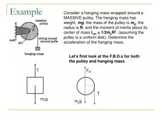
Example 4: Cascading of emergency stop devices by means of a safety module - Category 3 – PL e Safety Function • Emergency stop function, STO by actuation of an emergency stop device Functional Description • Hazardous movements or states are interrupted or prevented by actuation of an emergency stop device. As shown by Example 3 in Section 5.3.2, each emergency stop device triggers a safety function of its own. S1 is considered below as being representative of all the devices. S1 is evaluated in a safety module K1, which actuates two redundant contactor relays K2 and K3.
Example 4: Cascading of emergency stop devices by means of a safety module - Category 3 – PL e Functional Description Cont. • The signals from the emergency stop devices are read redundantly into the safety module K1 for fault detection. K1 also features internal test measures. The contactor relays K2 and K3 are also monitored in K1, by means of mechanically linked readback contacts. K2 and K3 are operated by switch S4 at each start-up command, approximately twice each month. An accumulation of more than two faults in the period between two successive actuations may lead to loss of the safety function. • It is not assumed that more than one emergency stop device is pressed simultaneously.
Example 4: Cascading of emergency stop devices by means of a safety module - Category 3 – PL e Design Features • Basic and well-tried safety principles are observed and the requirements of Category B are met. Protective circuits (e.g. contact protection) as described in the initial paragraphs of Chapter 8 are implemented. • The emergency stop devices S1, S2 and S3 are switching devices with direct opening contacts in accordance with IEC 60947-5-1, Annex K. • The supply conductors to the switching devices are laid separately or with protection. • The safety module K1 satisfies all requirements for Category 4 and PL e. • K2 and K3 possess mechanically linked contact elements to IEC 60947-5- 1,Annex L.