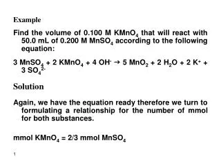
EXAMPLE
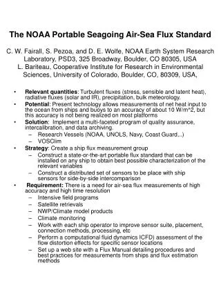
The NOAA Portable Seagoing Air-Sea Flux Standard C. W. Fairall, S. Pezoa, and D. E. Wolfe, NOAA Earth System Research Laboratory, PSD3, 325 Broadway, Boulder, CO 80305, USA L. Bariteau, Cooperative Institute for Research in Environmental Sciences, University of Colorado, Boulder, CO, 80309, USA,.

EXAMPLE
E N D
Presentation Transcript
The NOAA Portable Seagoing Air-Sea Flux StandardC. W. Fairall, S. Pezoa, and D. E. Wolfe, NOAA Earth System Research Laboratory, PSD3, 325 Broadway, Boulder, CO 80305, USAL. Bariteau, Cooperative Institute for Research in Environmental Sciences, University of Colorado, Boulder, CO, 80309, USA, • Relevant quantities: Turbulent fluxes (stress, sensible and latent heat), radiative fluxes (solar and IR), precipitation, bulk meteorology. • Potential: Present technology allows measurements of net heat input to the ocean from ships and buoys to an accuracy of about 10 W/m^2, but this accuracy is not being realized on most platforms • Solution: Implement a multi-faceted program of quality assurance, intercalibration, and data archiving. • Research Vessels (NOAA, UNOLS, Navy, Coast Guard,..) • VOSClim • Strategy: Create a ship flux measurement group • Construct a state-or-the-art portable flux standard that can be installed on any ship to obtain best possible characterization of the relevant variables • Construct a distributed set of sensors to be place with ship sensors for side-by-side intercomparison • Requirement: There is aneed for air-sea flux measurements of high accuracy and high time resolution • Intensive field programs • Satellite retrievals • NWP/Climate model products • Climate monitoring • Work with each ship operator to improve sensor suite, placement, connection methods, processing, etc • Perform a computational fluid dynamics ICFD) assessment of the flow distortion effects for specific sensor locations • Set up a web site with a Flux Manual detailing procedures and best practices for measurements from ships and flux estimation methods
EXAMPLE Recent sample comparison of ETL/PSD and Ship sensors from the R/V Roger Revelle: upper left, wind speed; upper right, wind direction; lower left, water temperature.; lower right, air temperature
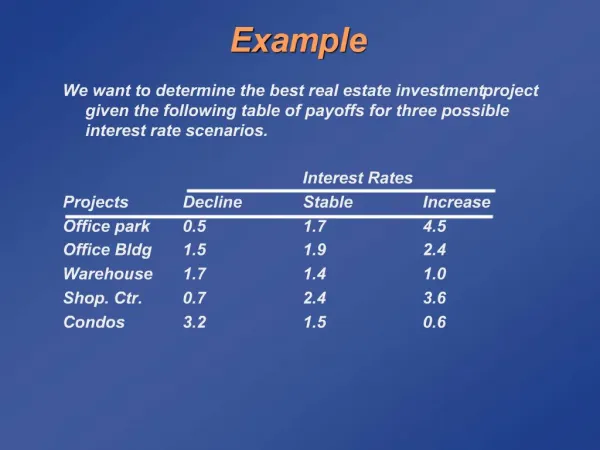
Table 1: Accuracy, precision and random error targets for SAMOS. Accuracy estimates are currently based on time scales for climate studies (i.e., ±10 W/m2 for Qnet on monthly to seasonal timescales). Several targets are still to be determined.[SS1] ACCURACY REQUIREMENTS [SS1]I still think it would be helpful to put these accuracy requirements into terms that one purchasing or installing a sensor can understand. I am not sure the best way to arrive at these accuracies, but I believe that the accuracy quoted by the manufacturer will not satisfy the above requirements.
Sensors • Anemometer • Open path Fast H2O/CO2 Analyzer • Laser Distance Wave Sensor • XYZ Angular velocity and linear Acceleration Sensor • Heading Gyrocompass • GPS • Met Campbell • T/RH air temperature/humidity • Optical Raingauge • Pressure sensor • PIR Longwave radiative flux • PSP Solar radiative flux • Surface water temperature
Instrument Specifications • Sonic Anemometer – GILL instruments Ltd • Omnidirectional R3 Ultrasonic Anemometer – serial • interface • Open Path CO2 / HO2 Analyzer – LICOR Inc. • model #7500 – serial interface • Laser Distance Sensor - RIEGL • model #LD90-3100VHS-FLP -serial interface • XYZ Motion Sensor – Systron and Donner • model #MP-GDDDQBBB-100 – analog output • Gyrocompass – Robertson Marine Electronics • model #RGC10 – analog output • GPS Smart Antenna - GARMIN • model #35/36 TrackPak – serial interface • Air T/RH - Vaisala • model # HMP-230 T/RH – analog output • Optical Sensor - Optical Scientific, Inc. • model #ORG-815-DA analog output • Precision Infrared Radiometer - Eppley • model #PIR - analog output • Precision Spectral Pyranometer - Eppley • model # PSP - analog output • Surface water Sensor – YSI Incorporated • Super- Stable Thermistor #46040 – analog output • Cloud Ceilometer – Vaisala • model #CT25K – serial interface • Air Pressure - Vaisala Pressure sensor • Model PTB220
Wireless Communications R/V Ronald Brown Flux System. Wireless transmitter are connected to : Sonic Licor Laser wave gauge R/V Ronald Brown Flux System Wireless receivers and Interface box on 2nd deck starboard side
Wireless Specifications • Each serial interface instrument is connected in a point • to point network topology with its own address identity. • A standard 2.4 GHz transmit frequency with spread • interfacing protocol. • The radio modem are build by MAxStream • with RS-232 PC interface. • The interface is set for all set of instruments as • 9600, 8,none,1 stop • The sampling rate are: • Sonic Anemometer 10Hz • Open Path CO2 / HO2 Analyzer 10Hz • Laser Distance Sensor 1Hz
Tilt-Stabilized Radiative Flux Measurements • The Stabilized stand alone system consist of: • 2 axis motion controller from Galil model #DMC 2020 • Power Amplifier/ Interface from Galil model #AMP-19520 • Solid State Vertical Gyro from Crossbow model VG400MA-100 • Servo motors from Parker
Motion-Corrected Winds and Turbulence Example:Vertical Velocity Plot of 86 s of datafrom the R/V Seward Johnson during RICO 2005: the upper panel shows the measured sonic vertical velocity (blue line) and the computed vertical velocity corrections from PSD (J.B.Edson and J.Hare routines) and the POS-MV ship system (red, green, and black lines). The bottom panel shows the true vertical velocity after removal of computed motion from the raw anemometer signal. The residual offset is a mean tilt of the flow caused by the ship structure.