Code generation and Instruction Selection
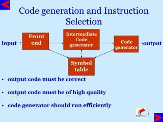
Code generation and Instruction Selection. Intermediate Code generator. Front end. output code must be correct output code must be of high quality code generator should run efficiently. Code generator. input. output. Symbol table. Issues in the design of code generator.

Code generation and Instruction Selection
E N D
Presentation Transcript
Code generation and Instruction Selection Intermediate Code generator Front end • output code must be correct • output code must be of high quality • code generator should run efficiently Code generator input output Symbol table
Issues in the design of code generator • Input: Intermediate representation with symbol table assume that input has been validated by the front end • target programs : • absolute machine language fast for small programs • relocatable machine code requires linker and loader • assembly code requires assembler, linker, and loader
Instruction Selection • Instruction selection • uniformity • completeness • Instruction speed • Register allocation Instructions with register operands are faster • store long life time and counters in registers • temporary locations • Even odd register pairs • Evaluation order
Instruction Selection • straight forward code if efficiency is not an issue a=b+c Mov b, R0 d=a+e Add c, R0 Mov R0, a Mov a, R0 can be eliminated Add e, R0 Mov R0, d a=a+1 Mov a, R0 Inc a Add #1, R0 Mov R0, a
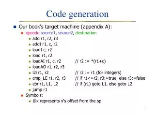
Target Machine • Byte addressable with 4 bytes per word • It has n registers R0, R1, ..., Rn-l • Two address instructions of the form opcode source, destination • Usual opcodes like move, add, sub etc. • Addressing modes MODE FORM ADDRESS Absolute M M register R R index c(R) c+cont(R) indirect register *R cont(R) indirect index *c(R) cont(c+cont(R)) literal #c c
Basic blocks • sequence of statements in which flow of control enters at beginning and leaves at the end • Algorithm to identify basic blocks • determine leader • first statement is a leader • any target of a goto statement is a leader • any statement that follows a goto statement is a leader • for each leader its basic block consists of the leader and all statements up to next leader
Flow graphs • add control flow information to basic blocks • nodes are the basic blocks • there is a directed edge from B1 to B2 if B2 can follow B1 in some execution sequence • there is a jump from the last statement of B1 to the first statement of B2 • B2 follows B1 in natural order of execution • initial node: block with first statement as leader
Next use information • for register and temporary allocation • remove variables from registers if not used • statement X = Y op Z defines X and uses Y and Z • scan each basic blocks backwards • assume all temporaries are dead on exit and all user variables are live on exit
Algorithm to compute next use information • Suppose we are scanning i : X := Y op Z in backward scan • attach to i, information in symbol table about X, Y, Z • set X to not live and no next use in symbol table • set Y and Z to be live and next use in i in symbol table
Example 1: t1 = a * a 2: t2 = a * b 3: t3 = 2 * t2 4: t4 = t1 + t3 5: t5 = b * b 6: t6 = t4 + t5 7: X = t6
Example Symbol Table STATEMENT 7: no temporary is live 6: t6:use(7), t4 t5 not live 5: t5:use(6) 4: t4:use(6), t1 t3 not live 3: t3:use(4), t2 not live 2: t2:use(3) 1: t1:use(4) Use in 4 dead dead Use in 3 dead Use in 4 dead Use in 6 dead Use in 6 dead Use in 7
Example … 1 2 t1 1: t1 = a * a 2: t2 = a * b 3: t2 = 2 * t2 4: t1 = t1 + t2 5: t2 = b * b 6: t1 = t1 + t2 7: X = t1 t2 3 t3 4 5 t4 t5 6 t6 7
Code Generator • consider each statement • remember if operand is in a register • Register descriptor • Keep track of what is currently in each register. • Initially all the registers are empty • Address descriptor • Keep track of location where current value of the name can be found at runtime • The location might be a register, stack, memory address or a set of those
Code Generation Algorithm for each X = Y op Z do • invoke a function getreg to determine location L where X must be stored. Usually L is a register. • Consult address descriptor of Y to determine Y'. Prefer a register for Y'. If value of Y not already in L generate Mov Y', L • Generate op Z', L Again prefer a register for Z. Update address descriptor of X to indicate X is in L. If L is a register update its descriptor to indicate that it contains X and remove X from all other register descriptors. • If current value of Y and/or Z have no next use and are dead on exit from block and are in registers, change register descriptor to indicate that they no longer containY and/or Z.
Function getreg • If Y is in register (that holds no other values) and Y is not live and has no next use after X = Y op Z then return register of Y for L. 2. Failing (1) return an empty register • Failing (2) if X has a next use in the block or op requires register then get a register R, store its content into M (by Mov R, M) and use it. 4. else select memory location X as L
Example Stmt code reg desc addr desc t1=a-b mov a,R0 R0 contains t1 t1 in R0 sub b,R0 t2=a-c mov a,R1 R0 contains t1 t1 in R0 sub c,R1 R1 contains t2 t2 in R1 t3=t1+t2add R1,R0 R0 contains t3 t3 in R0 R1 contains t2 t2 in R1 d=t3+t2add R1,R0 R0 contains d d in R0 mov R0,d d in R0 and memory
Conditional Statements • branch if value of R meets one of six conditions negative, zero, positive, non-negative, non-zero, non-positive if X < Y goto Z Mov X, R0 Sub Y, R0 Jmp negative Z • Condition codes: indicate whether last quantity computed or loaded into a location is negative, zero, or positive
Conditional Statements … • Compare instruction: sets the codes without actually computing the value • Cmp X, Y sets condition codes to positive if X > Y and so on if X < Y goto Z Cmp X, Y CJL Z • maintain a condition code descriptor: tells the name that last set the condition codes X =Y + Z Mov Y,R0 if X < 0 goto L Add Z, R0 Mov R0, X CJN L
DAG representation of basic blocks • useful data structures for implementing transformations on basic blocks • gives a picture of how value computed by a statement is used in subsequent statements • good way of determining common sub-expressions • A dag for a basic block has following labels on the nodes • leaves are labeled by unique identifiers, either variable names or constants • interior nodes are labeled by an operator symbol • nodes are also optionally given a sequence of identifiers for labels
DAG representation: example t6 prod + • t1 := 4 * i • t2 := a[t1] • t3 := 4 * i • t4 := b[t3] • t5 := t2 * t4 • t6 := prod + t5 • prod := t6 • t7 := i + 1 • i := t7 • if i <= 20 goto (1) t5 prod0 * (1) t4 t2 [ ] [ ] <= t1 t3 t7 i + 20 a b * 1 i0 4
Code Generation from DAG S1 = 4 * i S2 = addr(A)-4 S3 = S2[S1] S5 = addr(B)-4 S6 = S5[S4] S7 = S3 * S6 prod = prod + S7 I = I + 1 If I <= 20 goto (1) S1 = 4 * i S2 = addr(A)-4 S3 = S2[S1] S4 = 4 * i S5 = addr(B)-4 S6 = S5[S4] S7 = S3 * S6 S8 = prod+S7 prod = S8 S9 = I+1 I = S9 If I <= 20 goto (1)
Rearranging order of the code X - • Consider following basic block t1 = a + b t2 = c + d t3 = e –t2 X = t1 –t3 and its DAG t3 t1 - + t2 e + b a d c
Rearranging order … Rearranging the code as t2 = c + d t3 = e –t2 t1 = a + b X = t1 –t3 gives MOV c, R0 ADD d, R0 MOV e, R1 SUB R0, R1 MOV a, R0 ADD b, R0 SUB R1, R0 MOV R1, X Three adress code for the DAG (assuming only two registers are available) MOV a, R0 ADD b, R0 MOV c, R1 ADD d, R1 MOV R0, t1 MOV e, R0 SUB R1, R0 MOV t1, R1 SUB R0, R1 MOV R1, X Register spilling Register reloading
Peephole Optimization • target code often contains redundant instructions and suboptimal constructs • examine a short sequence of target instruction (peephole) and replace by a shorter or faster sequence • peephole is a small moving window on the target systems
Peephole optimization examples… Redundant loads and stores • Consider the code sequence Move R0, a Move a, R0 • Instruction 2 can always be removed if it does not have a label.
Peephole optimization examples… Unreachable code • Consider following code sequence #define debug 0 if (debug) { print debugging info } this may be translated as if debug = 1 goto L1 goto L2 L1: print debugging info L2: Eliminate jump over jumps if debug <> 1 goto L2 print debugging information L2:
Unreachable code example … constant propagation if 0 <> 1 goto L2 print debugging information L2: Evaluate boolean expression. Since if condition is always true the code becomes goto L2 print debugging information L2: The print statement is now unreachable. Therefore, the code becomes L2:
Peephole optimization examples… • flow of control: replace jump sequences goto L1 … … L1 : goto L2 • Simplify algebraic expressions remove x := x+0 or x:=x*1 goto L2 … … L1: goto L2 by
Peephole optimization examples… • Strength reduction • Replace X^2 by X*X • Replace multiplication by left shift • Replace division by right shift • Use faster machine instructions replace Add #1,R by Inc R
Code Generator Generator • Code generation by tree rewriting • target code is generated during a process in which input tree is reduced to a single node • each rewriting rule is of the form replacement template { action} where • replacement is a single node • template is a tree • action is a code fragment
Instruction set for a hypothetical machine + R R + R ^ := M R’ R R’ d R R R’ Move R’@, R Add R’, R Move R’, R@ Add #d, R + := R R M d R ^ Move #d, R + R + R’ ^ R’ d + R d Move R’@(d), R Move R’, R@(d) R’ d Add R’@(d), R
Example IR tree for A:=B+C+9 := + + + ^ a R0 R0 is the base register + 9 ^ R0 b + a, b, c are offsets of Variables A, B, C R0 c
Example … Generate Move #a, R1 := + + + ^ a R0 R1 matches move #d, R + 9 ^ R0 b + R0 c
Example … Generate Move #a, R1 Add R0, R1 := + + + R1 + ^ R0 R0 R1 R1 matches Add R’, R + 9 ^ R0 b + R0 c
Example … Generate Move #a, R1 Add R0, R1 Add R0@(b), R2 := + R1 R2 + ^ ^ matches Add R@(d), R’ + + 9 ^ R0 b R0 b + R0 c
Example … Generate Move #a, R1 Add R0, R1 Add R0@(b), R2 Add R0@(c), R3 := + R1 + R2 R3 9 ^ ^ matches Add R@(d), R’ + + R0 c R0 c
Example … Generate Move #a, R1 Add R0, R1 Add R0@(b), R2 Add R0@(c), R3 Add #9, R3 := + R1 + R2 R3 9 9 R3 matches Add #d, R
Example … Generate Move #a, R1 Add R0, R1 Add R0@(b), R2 Add R0@(c), R3 Add #9, R3 Add R3, R2 := + + R2 R1 R2 R2 R3 R3 matches Add R’, R
Example … Generate Move #a, R1 Add R0, R1 Add R0@(b), R2 Add R0@(c), R3 Add #9, R3 Add R3, R2 Move R2, R1@ M := := R2 R1 R2 R1 matches Add R’, R@
Example Generate Move #9, R1 := + + + ^ R0 a + 9 9 R1 ^ matches move #d, R R0 b + R0 c
Example … Generate Move #9, R1 Add R0@(c), R1 := + + ^ + R0 a + R1 R1 ^ ^ matches add R@(d), R’ R0 b + + R0 c R0 c
Example … Generate Move #9, R1 Add R0@(c), R1 Add R0@(b), R1 := + + + R1 ^ ^ R0 R1 R1 a matches add R@(d), R’ + + R0 b R0 b
Example … Generate Move #9, R1 Add R0@(c), R1 Add R0@(b), R1 Move R1, R0@(a) M := + + R1 R1 matches Move R, R’@(d) R0 R0 a a