Code Generation
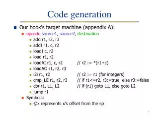
Code Generation. Code generation. Source Code. Front end. Code Optimizer. Code Generator. Intermediate Code. Intermediate Code. Symbol Table. Target Code. Code generator. Back end compiler module Takes IR as input Produces target code

Code Generation
E N D
Presentation Transcript
Code generation Source Code Front end Code Optimizer Code Generator Intermediate Code Intermediate Code Symbol Table Target Code
Code generator • Back end compiler module • Takes IR as input • Produces target code • Which should solve the problem with the results as expected in the source code • Utilizes hardware resources efficiently • Major issues • Instruction selection • Register allocation • Instruction ordering
Input to the code Generator • Intermediate Representation • Quadruples, triples, DAGs etc. • Symbol table – to generate run time addresses of the data objects using the computed offset for the names in the IR
Generating Run time address via the Symbol Table t1 = b * c = x = a + t1 x + a * b c All names are the pointers to the corresponding symbol table
Generating Run time address via the Symbol Table Call stack Space for t1 Space for c Space for b Stack pointer Space for a Space for x 3 address code Run time space for b is computed as contents(Stack Pointer) + space for fixed fields in the activation record + offset (from Symbol Table)
Code Generator • Produces relocatable addresses • Addresses are used for binding names to the locations (call stack space allocation) • Uses instructions to fetch the data from memory addresses to the registers • Registers are limited in number, hence cannot keep all values at a time • Code generator must generate code that makes optimum use of the registers [will be discussed during ‘register allocation’]
Instruction selection • Depends on the instructions available for the target machine • If efficiency is not a issue then simple code templates applied on IR produce the code • Example a=b+c • template for code generation LD r1,b Add r1,r1,c ST a, r1 Registers are not the physical registers until the register allocation phase Instruction selection assumes arbitrary number of registers are available
Instruction selection:Code Redundancy • Example IR a=b+c d=a+e • Applying Code Template on both of the above three address codes • LD r1, b • Add r1, r1, c • ST a, r1 • ST a, r1 • LD r2, a • Redundant code • LD r2, a • Add r2, r2, e • ST d, r2
Instruction Selection • A simple template based translation of the IR may lead to correct but unacceptably inefficient target code • Example : given IR a=a+1 Apply template : LD r1,a Add r1,r1,#1 ST a, r1 • An instruction ‘Inc’ can do the same task in less cost
Instruction selection • Requires knowledge of the context for selecting appropriate instruction for an intermediate code • Requires costs associated with each instruction • Instruction selection can be modeled as tree pattern matching process
A simple target machine model • Load instructions : • Store instructions • Computation instructions • Unconditional jumps • Conditional jumps LD destination, source ST destination, source OP destination, source1, source2 BR L Bcondr,L Examples LD r0, a // loads the contents of the address a to register r0 ST b, r3 // stores the contents of the register r3 to the addr b Add r1,r1,c // adds the contents of reg r1 and addr. c & places in r1 BLTZ r0,L1 // if content of r0 is less than zero, branches the execution control to L1
Examples of the target machine code x = y –z LD R1, y LD R2, z SUB R1, R1, R2 ST x, R1 x = *p LD R1, p LD R2, 0(R1) ST x, R2 b = a[i] LD R1, i MUL R1, R1, 8 LD R2, a(R1) ST b, R2 if x < y goto L LD R1, x LD R2, y SUB R1, R1, R2 BLTZ R1, L
Register Allocation issues • Fastest computational units as are nearest to the CPU • More data in registers makes the operations faster • Registers are limited in number, hence need to be overwritten • Issues • Which registers to hold which variables • Which registers to be reused
Register allocation With 1 register • If IR is as follows t1 = a + b t2 = t1 * c t3 = t2 – d x = t1 + t3 LD R0, a ADD R0,R0,b MUL R0,R0,c SUB R0,R0,d !!!!!!!!!! We can’t get back the value computed as t1 LD R0, a ADD R0,R0,b ST t1,R0 MUL R0,R0,c SUB R0,R0,d ADD R0,R0,t1 ST x, R0 Cost of the code increases
Register allocation With 2 registers • If IR is as follows t1 = a + b t2 = t1 * c t3 = t2 – d x =t1 + t3 LD R0, a ADD R0,R0,b MUL R1,R0,c SUB R1,R1,d ADD R0, R0, R1 ST X, R0 Cost of the code decreases More number of Registers are needed Questions : How long can a register hold a value? When is the need to write back the value in register to the memory location?
Cost of instructions • For simplicity, we take the cost of an instruction to be one plus the costs associated with the addressing modes of the operands. • Addressing modes involving registers have zero additional cost, while those involving a memory location or constant in them have an additional cost f one. • For example, • LD R0, R1cost = 1 • LD R0, M cost = 2 • LD R1, *100(R2) cost = 3
Recall Logical Space • Partitioned into four code and data areas: • Code - holds the executable target code. • Static - for holding global constants and other data generated by the compiler. • Heap - for holding data objects that are allocated and freed during program execution. • Stack - for holding activation records as they are created and popped off during procedure calls and returns.
Example function definition and call int add3(int x, int y, int z) { int sum; sum = x + y + z; return sum; } …….statements…S1.. s = add3(20,3,30); …….statements…S2.. IR for S1 Param 20 Param 3 Param 30 Call callee IR for S2 Intermediate code t1 = x + y t2 = t1+ z; return t1;
Three address instructions used • call callee • return • halt • action The size and layout of activation records are determined by the code generator via the information stored in the symbol table
Allocating stack space to the activation records • Use a register called SP to maintain top of the stack • Load SP with the start address of the stack (initialize stack pointer) LD SP, #stackstart • Allocate space to the activation record when a function is called • On return, the SP is modified by adding size of the activation record
Visualizing the stack and code areas Let the code area start from location 100 Initially PC is 100 Assume the highest end as address 300 Stack starts from here Initially SP is 300
stack and code areas Function call is at location 105 PC is 105 Should branch to 124 PC is 106 Return address Return address 106 Initially SP is 300
Understanding target machine instructions for function calls and return sequences • initialize stack pointer LD SP, #300 • Stack pointer for the new activation record SUB SP, #caller.recordsize • Preserving the return address on call callee LD *0(SP),PC PC has the address of the next instruction, should be placed in the beginning of the activation record of the callee
Target machine instructions • Branching back to the return address BR *0(SP) // contents(0 + contents(SP)) //holding the return address • Pop off activation record of the callee ADD SP,SP,#callee.recordsize//freeing space //reuse stack space
Intermediate code for the callee t1 = x + y t2 = t1+ z; return t1; Partial CODE for the callee code for the callee 124 : SUB R0,SP,#-4 125 : LD R1, *0(R0) //x 126: LD R2, *4(R0) //y 127: ADD R1,R1,R2 //t1 t1 = x + y Symbol table entries for offsets 128 : LD R2, *8(R0) //z 129: ADD R1,R1,R2 130 : BR *0(SP) //return t2 = t1 + z Home Work How will you apply parameter passing technique (call by value)?
IR for S1 Param 20 Param 3 Param 30 Call add3 IR for S2 Partial CODE for the caller code for the caller 101: SUB R0,SP,#-4 //fixed 102: ST *offset1(R0),#20 103: ST *offset2(R0),#3 104: ST *offset3(R0),#30 105: BR 124 Writing the values of the actual parameters at the designated memory locations
Other links • Old stack pointer needs to be preserved in callee’s activation record to access e.g. parameter values, copying return values etc
Next Class • Liveness Analysis