Analog vs. Digital Circuits & Comparators: Understanding Electronic Instrumentation
Explore the differences between analog and digital circuits, the role of comparators and Schmitt triggers, and the basics of combinational and sequential logic devices in electronic instrumentation.

Analog vs. Digital Circuits & Comparators: Understanding Electronic Instrumentation
E N D
Presentation Transcript
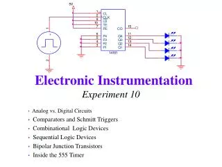
Experiment 10 Analog vs. Digital Circuits Comparators and Schmitt Triggers Combinational Logic Devices Sequential Logic Devices Bipolar Junction Transistors Inside the 555 Timer
Analog Circuits vs. Digital Circuits • Ananalog signal is an electric signal whose value varies continuously over time. • A digital signal can take on only finite values as the input varies over time. Electronic Instrumentation
A binary signal, the most common digital signal, is a signal that can take only one of two discrete values and is therefore characterized by transitions between two states. • In binary arithmetic, the two discrete values f1 and f0 are represented by the numbers 1 and 0, respectively. Electronic Instrumentation
In binary voltage waveforms, these values are represented by two voltage levels. • In TTL convention, these values are nominally 5V and 0V, respectively. • Note that in a binary waveform, knowledge of the transition between one state and another is equivalent to knowledge of the state. Thus, digital logic circuits can operate by detecting transitions between voltage levels. The transitions are called edges and can be positive (f0 to f1) or negative (f1 to f0). Electronic Instrumentation
In this section we will use op-amps to create binary signals. Comparators are the simplest way to create a binary signal with an op amp. They take advantage of the very high gain of the chip to force it to saturate either high (VS+) or low (VS-) creating two (binary) states. Schmitt Triggers are a modified version of a comparator which uses a voltage divider to improve the performance of the comparator in the presence of noise. Comparators and Schmitt Triggers Electronic Instrumentation
Op-Amp Comparator • The prototype of op-amp switching circuits is the op-amp comparator. • The circuit does not employ feedback. Electronic Instrumentation
Because of the large gain that characterizes open-loop performance of the op-amp (A > 105), any small difference between the input voltages will cause large outputs; the op-amp will go into saturation at either extreme, according the voltage supply values and the polarity of the voltage difference. • One can take advantage of this property to generate switching waveforms. • Consider the following. Non-inverting Op-Amp Comparator Electronic Instrumentation
The comparator is perhaps the simplest form of an analog-to-digital converter, i.e., a circuit that converts a continuous waveform to discrete values. The comparator output consists of only two discrete levels. Input and Output of Non-Inverting Comparator Vsat = ± 13.5 volts V = 1 volt Electronic Instrumentation
It is possible to construct an inverting comparator by connecting the non-inverting terminal to ground and connecting the input to the inverting terminal. Input and Output of Inverting Comparator Electronic Instrumentation
Comparator with Offset • A simple modification of the comparator circuit consists of connecting a fixed reference voltage to one of the input terminals; the effect of the reference voltage is to raise or lower the voltage level at which the comparator will switch from one extreme to the other. Electronic Instrumentation
Below is the waveform of a comparator with a reference voltage of 0.6 V and an input voltage of sin(ωt). • Note that the comparator output is no longer a symmetric square wave. Electronic Instrumentation
Another useful interpretation of the op-amp comparator can be obtained by considering its input-output transfer characteristic. Non-Inverting Zero-Reference (no offset) Comparator often called a zero-crossing comparator Electronic Instrumentation
Shown below is the transfer characteristic for a comparator of the inverting type with a nonzero reference voltage. Electronic Instrumentation
Comparator Response to Noisy Inputs Note how the output swings between high and low. Electronic Instrumentation
Schmitt Trigger • One very effective way of improving the performance of the comparator is by introducing positive feedback. Positive feedback can increase the switching speed of the comparator and provide noise immunity at the same time. • The voltage range over which the signal does not switch is called the hysteresis (In this case, h=2d) Can you explain how this works? Electronic Instrumentation
In effect, the Schmitt trigger provides a noise rejection range equal to ± Vsat [R2 / (R2 + R1)] within which the comparator cannot switch. • Thus if the noise amplitude is contained within this range, the Schmitt trigger will prevent multiple triggering. Electronic Instrumentation
If it is desired to switch about a voltage other than zero, a reference voltage can also be connected to the non-inverting terminal. In this case, d+ is not equal to d-, and the hysteresis is given by h=d+ + d- Switching levels for the Schmitt Trigger are: positive-going transition negative-going transition Electronic Instrumentation
Combinational Logic Devices • Logic Gates perform basic logic operations, such as AND, OR and NOT, on binary signals. • In this class, we use them as black boxes. This means that we do not worry about how these chips are built inside, but only about what output they produce for all possible inputs. • In order to show this behavior, we use truth tables, which show the output for all input combinations. • The outputs of combinational logic gates depend only on the instantaneous values of the inputs. Electronic Instrumentation
Logic Gates Electronic Instrumentation
Logic Gate Example: XOR Question: What common household switch configuration corresponds to an XOR? Electronic Instrumentation
Boolean Algebra • The variables in a boolean, or logic, expression can take only one of two values, 0 (false) and 1 (true). • We can also use logical mathematical expressions to analyze binary operations, as well. Electronic Instrumentation
The basis of boolean algebra lies in the operations of logical addition, or the OR operation, and logical multiplication, or the AND operation. • OR Gate • If either X or Y is true (1), then Z is true (1) • AND Gate • If both X and Y are true (1), then Z is true (1) • Logic gates can have an arbitrary number of inputs. • Note the similarities to the behavior of the mathematical operators plus and times. Electronic Instrumentation
Laws of Boolean Algebra Electronic Instrumentation
DeMorgan’s Laws Electronic Instrumentation
Using DeMorgan’s Laws Important Principal based on DeMorgan’s Laws: Any logic function can be implemented by using only OR and NOT gates, or only AND and NOT gates. Electronic Instrumentation
Sequential Logic Devices • In a sequential logic device, the timing or sequencing of the input signals is important. Devices in this class include flip-flops and counters. • Positive edge-triggered devices respond to a low-to-high (0 to 1) transition, and negative edge-triggered devices respond to a high-to-low (1 to 0) transition. Electronic Instrumentation
Flip-Flops • A flip-flop is a sequential device that can store and switch between two binary states. • It is called a bistable device since it has two and only two possible output states: 1 (high) and 0 (low). • It has the capability of remaining in a particular state (i.e., storing a bit) until the clock signal and certain combinations of the input cause it to change state. Electronic Instrumentation
Simple Flip Flop Example: The RS Flip-Flop Q = 0 Note that the output depends on three things: the two inputs and the previous state of the output. Q = 1 Electronic Instrumentation
Inside the R-S Flip Flop Note that the enable signal is the clock, which regularly pulses. This flip flop changes on the rising edge of the clock. It looks at the two inputs when the clock goes up and sets the outputs according to the truth table for the device. Electronic Instrumentation
Inside the J-K Flip Flop Note this flip flop, although structurally more complicated, behaves almost identically to the R-S flip flop, where J(ump) is like S(et) and K(ill) is like R(eset). The major difference is that the J-K flip flop allows both inputs to be high. In this case, the output switches state or “toggles”. Electronic Instrumentation
Binary Counters • Binary Counters do exactly what it sounds like they should. They count in binary. • Binary numbers are comprised of only 0’s and 1’s. Electronic Instrumentation
Binary – Decimal -- Hexadecimal Conversion 10110101110001011001110011110110 binary number 11 5 12 5 9 12 15 6 equivalent base 10 value for each group of 4 consecutive binary digits (bits) B 5 C 5 9 C F 6 corresponding hexadecimal (base 16) digit equivalent hexadecimal number B5C59CF6 Decimal 8 = 1x23 + 0x22 + 0x21 +0x20 = 01000 in Binary Calculator Applet Electronic Instrumentation
Binary Counters are made with Flip Flops Each flip flop corresponds to one bit in the counter. Hence, this is a four-bit counter. Electronic Instrumentation
Typical Output for Binary Counter • Note how the Q outputs form 4 bit numbers Electronic Instrumentation
Bipolar Junction Transistors • The bipolar junction transistor (BJT) is the salient invention that led to the electronic age, integrated circuits, and ultimately the entire digital world. The transistor is the principal active device in electrical circuits. • When inputs are kept relatively small, the transistor serves as an amplifier. When the transistor is overdriven, it acts as a switch, a mode most useful in digital electronics. Electronic Instrumentation
B • There are two types of BJTs, npn and pnp, and the three layers are called collector (C), base (B), and emitter (E). npn transistor E C • All current directions are reversed from the npn-type to the pnp-type. • A BJT consists of three adjacent regions of doped silicon, each of which is connected to an external lead. The base, a very thin slice of one type, is sandwiched by the complementary pair of the other type, hence the name bipolar. Electronic Instrumentation
MOSFET • Applying a gate voltage that exceeds the threshold voltage opens up the channel between the source and the drain • This is from an excellent collection of java applets at SUNY Buffalo http://jas.eng.buffalo.edu/ Electronic Instrumentation
pnp and npn transistors Note: The npn-type is the more popular; it is faster and costs less. VCE < 0 VBE < 0 VCE > 0 VBE > 0 pnp BJT npn BJT Apply voltage LOW to base to turn ON Apply voltage HIGH to base to turn ON Electronic Instrumentation
Regions of the npn BJT • Cutoff Region • Not enough voltage at B for the diode to turn on. • No current flows from C to E and the voltage at C is Vcc. • Saturation Region • The voltage at B exceeds 0.7 volts, the diode turns on and the maximum amount of current flows from C to E. • The voltage drop from C to E in this region is about 0.2V but we often assume it is zero in this class. • Active Region • As voltage at B increases, the diode begins to turn on and small amounts of current start to flow through into the doped region. A larger current proportional to IB, flows from C to E. • As the diode goes from the cutoff region to the saturation region, the voltage from C to E gradually decreases from Vcc to 0.2V. Electronic Instrumentation
The diode is controlled by the voltage at B. • When the diode is completely on, the switch is closed. This is the saturation region. • When the diode is completely off, the switch is open. This is the cutoff region. • When the diode is in between we are in the active region. Model of the npn BJT Electronic Instrumentation
npn Common Emitter Characteristics IC = βIB VBE = 0.7 V VBE < 0.6 V Electronic Instrumentation
Using the transistor as a switch Electronic Instrumentation
Building logic gates with transistors Electronic Instrumentation
Inside the 555 Timer animation Electronic Instrumentation