Chapter 5 GEOPHYSICS
Chapter 5 GEOPHYSICS. Mechanical Wave Measurements Electromagnetic Wave Techniques. Geophysical Methods. Mechanical Wave Measurements Crosshole Tests (CHT) Downhole Tests (DHT) Spectral Analysis of Surface Waves Seismic Refraction Suspension Logging Electromagnetic Wave Techniques

Chapter 5 GEOPHYSICS
E N D
Presentation Transcript
Chapter 5GEOPHYSICS Mechanical Wave Measurements Electromagnetic Wave Techniques
Geophysical Methods • Mechanical Wave Measurements • Crosshole Tests (CHT) • Downhole Tests (DHT) • Spectral Analysis of Surface Waves • Seismic Refraction • Suspension Logging • Electromagnetic Wave Techniques • Ground Penetrating Radar (GPR) • Electromagnetic Conductivity (EM) • Surface Resistivity (SR) • Magnetometer Surveys (MT)
Mechanical Wave Geophysics • Nondestructive measurements (gs < 10-4%) • Both borehole geophysics and non-invasive types (conducted across surface). • Measurements of wave dispersion: velocity, frequency, amplitude, attenuation. • Determine layering, elastic properties, stiffness, damping, and inclusions • Four basic wave types: Compression (P), Shear (S), Rayleigh (R), and Love (L).
Mechanical Wave Geophysics • Compression (P-) wave is fastest wave; easy to generate. • Shear (S-) wave is second fastest wave. Is directional and polarized. Most fundamental wave to geotechnique. • Rayleigh (R-) or surface wave is very close to S-wave velocity (90 to 94%). Hybrid P-S wave at ground surface boundary. • Love (L-) wave: interface boundary effect
Mechanical Body Waves Initial P-wave S-wave
S R P RSP Mechanical Body Waves Amplitude Time Oscilloscope Source Receiver (Geophone)
Geophysical Equipment Seismograph Spectrum Analyzer Portable Analyzer Velocity Recorder
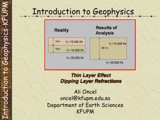
t1 t2 t3 t4 Determine depth to rock layer, zR Vertical Geophones Source (Plate) x1 x2 x3 x4 zR oscilloscope Seismic Refraction ASTM D 5777 Note: Vp1 < Vp2 Soil: Vp1 Rock: Vp2
1 Vp2 = 4880 m/s xc= 15.0 m 1 Vp1 = 1350 m/s Seismic Refraction Depth to Rock: zc = 5.65 m t values x values
Shear Wave Velocity, Vs • Fundamental measurement in all solids (steel, concrete, wood, soils, rocks) • Initial small-strain stiffness represented by shear modulus: G0 = rT Vs2(alias Gdyn = Gmax = G0) • Applies to all static & dynamic problems at small strains (gs < 10-6) • Applicable to both undrained & drained loading cases in geotechnical engineering.
Pump x = fctn(z) from inclinometers t Slope Inclinometer Slope Inclinometer Shear Wave Velocity: Vs = x/t Downhole Hammer (Source) Velocity Transducer (Geophone Receiver) x packer Oscilloscope Crosshole Testing ASTM D 4428 © Paul Mayne/GT Test Depth Note: Verticality of casing must be established by slope inclinometers to correct distances x with depth. PVC-cased Borehole PVC-cased Borehole
Pump Horizontal Plank with normal load x t z1 Hammer z2 packer Horizontal Velocity Transducers (Geophone Receivers) R12 = z12 + x2 R22 = z22 + x2 Shear Wave Velocity: Vs = R/t Oscilloscope Downhole Testing © Paul Mayne/GT Test Depth Interval Cased Borehole
In-Situ Surface Wave Testing Signal Analyzer Accelerometer Sensors Source Rayleigh Surface Waves Layer 1 Layer 2 Layer 3 Layer 4
Seismic Piezocone Test Vs fs u2 u1 qc Obtains Four Independent Measurements with Depth: Hybrid of Penetrometer with Downhole Geophysics • Cone Tip Stress, qt • Penetration Porewater Pressure,u • Sleeve Friction, fs • Arrival Time of Downhole Shear Wave, ts 60o
Automated Seismic Source • Electronically-actuated • Self-contained • Left and right polarization • Modified beam uses fin to enhance shear wave generation • Successfully tested to depths of 20m • Capable of being used with traditional impulse hammer
Downhole Shear Wave Velocity • Anchoring System • Automated Source • Polarized Wave • Downhole Vs with excellent soil coupling.
Complete Set of Shear Wave TrainsMud Island Site A, Memphis TN
Seismic DMTs at UMASS, Amherst 6 DMT 2 DMT 3 SDT 4 8 10 12
More Measurements is More Better
Geophysical Methods Electromagnetic Wave Techniques
Electromagnetic Wave Geophysics • Nondestructive methods • Non-invasive; conducted across surface. • Measurements of electrical & magnetic properties of the ground: resistivity (conductivity), permittivity, dielectric, and magnetic fields. • Cover wide spectrum in frequencies (10 Hz < f < 1022 Hz).
Electromagnetic Wave Geophysics • Surface Mapping Techniques: • Ground Penetrating Radar (GPR) • Electrical Resistivity (ER) Surveys • Electromagnetic Conductivity (EM) • Magnetometer Surveys (MS) • Downhole Techniques • Resistivity probes, MIPs, RCPTu • 2-d and 3-d Tomography
Ground Penetrating Radar (GPR) • GPR surveys conducted on gridded areas • Pair of transmitting and receiver antennae • Short impulses of high-freq EM wave • Relative changes in dielectric properties reflect differences in subsurface. • Depth of exploration is soil dependent (up to 30 m in dry sands; only 3 m in wet saturated clay)
Ground Penetrating Radar (GPR) Xadar Sensors & Software GeoRadar
Illustrative Results from Ground Penetrating Radar (GPR) Crossing an underground utility corridor
Illustrative Results of Ground Penetrating Radar (GPR) Geostratigraphy
Examples of Ground Penetrating Radar (GPR) Useful in Locating Underground Utilities
Electrical Resistivity (ER) Surveys • Resisitivity rR (ohm-m) is an electrical property. It is the reciprocal of conductivity • Arrays of electrodes used to measure changes in potential. • Evaluate changes in soil types and variations in pore fluids • Used to map faults, karst features (caves, sinkholes), stratigraphy, contaminant plumes.
Electrical Resisitivity Measurements What will be gained by changing electrode spacing? Depth of ER survey: i.e., greater spacing influences deeper
Magnetometer Surveys (MS) Measure relative changes in the earths' magnetic field across a site.
In-Situ Testing - Objectives • Select in-situ tests for augmenting, supplementing, and even replacing borings. • Realize the applicability of various in-situ methods to different soil conditions. • Recognize the complementary nature of in-situ direct push methods with conventional rotary drilling & sampling methods. • Recognize values for utilizing these methods and quality implications for their underuse.