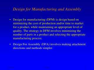
Chapter 5 Design for High Speed Automatic Assembly and Robot Assembly
1.06k likes | 2.35k Vues
Chapter 5 Design for High Speed Automatic Assembly and Robot Assembly. 5.1 INTRODUCTION. Fig . 5.1: The slightly asymmetrical threaded stud would not present significant problems in manual handling and insertion

Chapter 5 Design for High Speed Automatic Assembly and Robot Assembly
E N D
Presentation Transcript
Chapter 5Design for High Speed Automatic Assembly and Robot Assembly Dr. Mohammad Abuhaiba
5.1 INTRODUCTION Fig. 5.1: • The slightly asymmetrical threaded stud would not present significant problems in manual handling and insertion • For automatic handling an expensive vision system would be needed to recognize its orientation. • If the part were made symmetrical, automatic handling would be simple. Dr. Mohammad Abuhaiba
5.1 INTRODUCTION • if a part can be handled automatically, then it can usually be assembled automatically. • When we consider design for automation, we will be paying close attention to the design of the parts for ease of automatic feeding and orienting. Dr. Mohammad Abuhaiba
5.1 INTRODUCTION • In automatic assembly: • Time taken to complete an assembly does not control the assembly cost. • It is the rate at which the assembly machine or system cycles. • If the total rate (cost per unit time) for the machine or system and all the operators is known, the assembly cost can be calculated. • We shall be mainly concerned with: • Cost of all the equipment • Number of operators and technicians • Assembly rate at which the system is designed to operate • Apportion the cost of product assembly between the individual parts and, for each part; we shall need to know the cost of feeding and orienting and the cost of automatic insertion. Dr. Mohammad Abuhaiba
5.2 DESIGN OF PARTS FOR HIGH-SPEED FEEDING AND ORIENTING • Cost of feeding & orienting parts depends on: • Cost of the equipment required • Time interval between delivery of successive parts. • Time between delivery of parts: reciprocal of the delivery rate. • It is equal to cycle time of machine or system. • Let Fr= required delivery or feed rate (parts/min), then the cost of feeding each part Cf is given by Dr. Mohammad Abuhaiba
5.2 DESIGN OF PARTS FOR HIGH-SPEED FEEDING AND ORIENTING • Rf= cost (cents/s) of using feeding equipment • CF =feeder cost ($) • Eo= equipment factory overhead ratio • Pb = payback period in months • Sn= number of shifts worked per day • The constant 5760 = number of available seconds in one shift working for one month divided by 100 to convert dollars to cents. Dr. Mohammad Abuhaiba
5.2 DESIGN OF PARTS FOR HIGH-SPEED FEEDING AND ORIENTING Example: assume that a standard vibratory bowl feeder costs $5000, payback period is 30 months with 2 shifts working, factory equipment overheads are 100% (Eo = 2), we get • Rf = 5000 x 2/(5760 x 30 x 2) = 0.03 cent/s • It would cost 0.03 cents to use the equipment for 1 second. • Taking this figure as the rate for a "standard" feeder and assigning a relative cost factor Cr to any feeder under consideration, then Eq. (5.1) becomes Cf= 0.03(60/Fr)Cr (5.3) Dr. Mohammad Abuhaiba
5.2 DESIGN OF PARTS FOR HIGH-SPEED FEEDING AND ORIENTING • Feeding cost per part is inversely proportional to required feed rate and proportional to feeder cost. • For otherwise identical conditions, it would cost twice as much to feed each part to a machine with a 6 s cycle compared with the cost for a machine with a 3 s cycle. • This illustrates why it is difficult to justify feeding equipment for assembly systems with long cycle times. • It would cost twice as much to feed a part using a feeder costing $10,000 compared with a feeder costing $5000. Dr. Mohammad Abuhaiba
5.2 DESIGN OF PARTS FOR HIGH-SPEED FEEDING AND ORIENTING • Fig. 5.2: • The faster the parts are required, the lower the feeding cost. • This is true only as long as there is no limit on the speed at which a feeder can operate. • There is an upper limit to the feed rate obtainable from a particular feeder. • Fm= maximum feed rate Dr. Mohammad Abuhaiba
5.2 DESIGN OF PARTS FOR HIGH-SPEED FEEDING AND ORIENTING Dr. Mohammad Abuhaiba
5.2 DESIGN OF PARTS FOR HIGH-SPEED FEEDING AND ORIENTING Example: Let max feed rate from feeder = 10 parts/min. • If parts are required at a rate of 5 parts/min, feeder can simply be operated more slowly involving an increased feeding cost. • Suppose parts are required at a rate of 20 parts/min. • Two feeders could be used, each at a rate of 10 parts/min. • Feeding cost per part using two feeders to give twice max feed rate will be the same as one feeder delivering parts at its max feed rate. • If required feed rate is greater than max feed rate obtainable from one feeder, feeding cost becomes constant and equal to cost of feeding when the feeder is operating at its max rate. This is shown in Fig. 5.2 by the horizontal line. • If multiple feeders are used for increased feed rates, then the line will be saw-toothed as shown. Dr. Mohammad Abuhaiba
5.2 DESIGN OF PARTS FOR HIGH-SPEED FEEDING AND ORIENTING • Eq. (5.3) holds true only when required feed rate Fr<max feed rate Fm • when this is not the case feeding cost is given by Cf= 0.03(60/Fm)Cr (5.4) • Now max feed rate Fmis given by Fm= 1500 E/l parts/min (5.5) • E = orienting efficiency for the part • l (mm) = its overall dimension in the direction of feeding and where it is assumed that the feed speed is 25 mm/s. Dr. Mohammad Abuhaiba
5.2 DESIGN OF PARTS FOR HIGH-SPEED FEEDING AND ORIENTING The meaning of the orienting efficiency E: • Consider feeding of dies (cubes with faces numbered 1 to 6). • If no orientation is needed, the dies can be delivered at a rate of 1 per second from a vibratory bowl feeder. • If only those dies with the 6 side uppermost were of interest, • a vision system could be employed to detect all other orientations and a solenoid operated pusher could be used to reject them. • In this case the delivery rate would fall to an average of 1 die every 6 seconds or a feed rate of 1/6 per second. • The factor 1/6 is defined as the orienting efficiency E and it can be seen that the max feed rate is proportional to the orienting efficiency (Eq. (5.5)). Dr. Mohammad Abuhaiba
5.2 DESIGN OF PARTS FOR HIGH-SPEED FEEDING AND ORIENTING • If dies were doubled in size and that feed speed on the feeder track were unaffected. It would then take twice as long to deliver each die. • Max feed rate is inversely proportional to length of part in the feeding direction [Eq. (5.5)]. Dr. Mohammad Abuhaiba
5.2 DESIGN OF PARTS FOR HIGH-SPEED FEEDING AND ORIENTING • Eq. 5.4 shows that when Fr > Fm, the feeding cost per part is inversely proportional to Fm. • Under these circumstances, cost of feeding is inversely proportional to orienting efficiency and proportional to length of part in the feeding direction. • Automatic feeding and orienting methods are only applicable to "small" parts. • Parts larger than about 8” in their major dimension cannot usually be fed economically. Dr. Mohammad Abuhaiba
5.2 DESIGN OF PARTS FOR HIGH-SPEED FEEDING AND ORIENTING • When considering the design of a part and its feeding cost, the designer will know: • required feed rate Fr • dimensions of the part, l • The remaining two parameters that affect feeding cost, namely, the orienting efficiency E and the relative feeder cost Cr, will depend on: • part symmetry • types of features that define its orientation. • A portion of aclassificationsystem is presented in Figs. 5.3 to 5.5. Dr. Mohammad Abuhaiba
5.2 DESIGN OF PARTS FOR HIGH-SPEED FEEDING AND ORIENTING • Fig. 5.3: 1st digit of a 3-digit shape code. • Fig. 5.4: 2nd and 3rd digits are determined for a selection of rotational parts (1st digit 0, 1, or 2) and corresponding values of orienting efficiency E and relative feeder cost Cr. • Fig. 5.5: 2nd and 3rd digits are determined for a selection of non-rotational parts (1st digit 6, 7, or 8). Dr. Mohammad Abuhaiba
5.2 DESIGN OF PARTS FOR HIGH-SPEED FEEDING AND ORIENTING Dr. Mohammad Abuhaiba
5.2 DESIGN OF PARTS FOR HIGH-SPEED FEEDING AND ORIENTING Dr. Mohammad Abuhaiba
5.2 DESIGN OF PARTS FOR HIGH-SPEED FEEDING AND ORIENTING FIG. 5.5: 2nd & 3rd digits of geometrical classification for some non-rotational parts Dr. Mohammad Abuhaiba
5.3 EXAMPLE • Part shown in Fig. 5.6 is to be delivered to an automatic assembly station working at a 5 s cycle. • Use classification system and database to determine feeding cost assuming that cost of delivering simple parts at 1 per second using standard feeder of 0.03 cents per part. Dr. Mohammad Abuhaiba
5.3 EXAMPLE • A = 30 mm, B = 20 mm, and C = 15 mm • A/B = 1.5 and A/C = 2 • Fig. 5.3: A/B < 3 and A/C < 4, part is cubic non-rotational and is assigned a 1st digit of 8. • Fig. 5.5: part has no rotational symmetry about any of its axes. Dr. Mohammad Abuhaiba
5.3 EXAMPLE • Outline of part in X direction: • A step or projection in the basic rectangular shape • This feature alone can always be used to determine part's orientation. • This means that if the outline in the X direction is oriented as shown in Fig. 5.6, part can be in only one orientation • Therefore, 2nddigit of the classification is 4. • However, either groove apparent in the view in Y direction and step seen in the view in Z direction could also be used to determine the part's orientation. • Select feature giving smallest 3rd classification digit; in this case it is the step seen in X direction. • Thus appropriate column number in Fig. 5.5 is 0. • Three-digit code: 840 • Orienting efficiency: E = 0.15 • Relative feeder cost: Cr = 1 Dr. Mohammad Abuhaiba
5.3 EXAMPLE • Longest part dimension l = 30 mm • Orienting efficiency E = 0.15 • Eq. (5.5) gives max feed rate obtainable from one feeder • Fm =1500 E/ l = 1500x0.15/30 = 7.5 parts/min • From the cycle time of 5 s the required feed rate Fris 12 parts/min, which is higher than Fm. • Since Fr > Fmwe use Eq. (5.4) • Cr= 1 • Feeding cost Cf= 0.03(60/Fm)Cr = 0.03(60/7.5)1 = 0.24 cents Dr. Mohammad Abuhaiba
5.4 ADDITIONAL FEEDING DIFFICULTIES • Fig. 5.7: If edges of parts are thin, shingling or overlapping can occur during feeding, leading to problems with the use of orienting devices on feeder track Dr. Mohammad Abuhaiba
5.4 ADDITIONAL FEEDING DIFFICULTIES • Fig. 5.8:for each combination of features, an approximate additional relative feeder cost is given that should be taken into account in estimating the cost of automatic feeding. Dr. Mohammad Abuhaiba
5.5 HIGH-SPEED AUTOMATIC INSERTION • If a part can be sorted from bulk and delivered to a convenient location correctly oriented, a special-purpose mechanism or work head can usually be designed that will place it in the assembly. • Such work heads can generally be built to operate on a cycle as short as 1 second. • For assembly machines operating on cycles greater than 1 sec, automatic insertion cost Ciis given by • Fr= required assembly rate (or feed rate of parts) • Ri = cost (cents/s) of using the automatic work head Dr. Mohammad Abuhaiba
5.5 HIGH-SPEED AUTOMATIC INSERTION • The equipment rate Riis given by • Wc = work head cost ($) • Eo= equipment factory overhead ratio • Pb = payback period in months • Sn= number of shifts worked per day • Assuming a standard work head costs $10,000, payback period is 30 months with two shifts working, and factory equipment overheads are 100% (Eo = 2), we get • Ri = 10,000 x 2/(5760 x 30 x 2) = 0.06 cents/s Dr. Mohammad Abuhaiba
5.5 HIGH-SPEED AUTOMATIC INSERTION • It would cost 0.06 cents to use the equipment for 1 second. • Taking this figure as the rate for a "standard" work head and assign a relative cost factor Wrto any work head under consideration, then Eq. (5.6) becomes • Insertion cost is inversely proportional to required assembly rate and proportional to work head cost. Dr. Mohammad Abuhaiba
5.5 HIGH-SPEED AUTOMATIC INSERTION Dr. Mohammad Abuhaiba
5.6 EXAMPLE • Fig. 5.6: • part is inserted horizontally into the assembly in the direction of arrow Y • It is not easy to align and position • Not secured on insertion • Appropriate classification is row 1, column 2 in Fig. 5.9 • Automatic insertion code is thus 12, giving a relative work head cost of 1.6. • For a cycle time of 5 s, assembly rate Fris 12parts/min and Eq. (5.8) gives an insertion cost of: • Ci= 0.06(60/Fr) Wr= 0.06(60/12)1.6 = 0.48 cents • Total handling & insertion cost Ct= 0.24 + 0.48 = 0.72 cents Dr. Mohammad Abuhaiba
5.7 ANALYSIS OF AN ASSEMBLY • assembled at a rate of 9.6 per minute Dr. Mohammad Abuhaiba
5.7 ANALYSIS OF AN ASSEMBLY • FIG. 5.11: Completed worksheets for high-speed automatic assembly analysis of the assemblies in Fig. 5.10 - Original Design Dr. Mohammad Abuhaiba
5.7 ANALYSIS OF AN ASSEMBLY • FIG. 5.11: Completed worksheets for high-speed automatic assembly analysis of the assemblies in Fig. 5.10 – Re-Design Dr. Mohammad Abuhaiba
5.8 GENERAL RULES FOR PRODUCT DESIGN FOR AUTOMATION • The elimination of a part would eliminate: • a complete station on an assembly machine-including the parts feeder • special work head • associated portion of the transfer device Dr. Mohammad Abuhaiba
5.8 GENERAL RULES FOR PRODUCT DESIGN FOR AUTOMATION • Automation can be facilitated by the introduction of guides and chamfers. • Figs. 5.12 and 5.13 • Sharp corners are removed so that the part can be guided into its correct position during assembly leading to: • less control by the placement device or • can even eliminate the need for a placement device. Dr. Mohammad Abuhaiba
5.8 GENERAL RULES FOR PRODUCT DESIGN FOR AUTOMATION Dr. Mohammad Abuhaiba
5.8 GENERAL RULES FOR PRODUCT DESIGN FOR AUTOMATION Dr. Mohammad Abuhaiba
5.8 GENERAL RULES FOR PRODUCT DESIGN FOR AUTOMATION • Screws that tend to centralize themselves in the hole give the best results in automatic assembly: • Rolled thread point: very poor location; will not centralize without positive control on the outside diameter of the screws. • Header point: only slightly better than (1) if of correct shape. • Chamfer point: reasonable to locate. • Dog point: reasonable to locate • Cone point: very good to locate. • Oval point: very good to locate. Dr. Mohammad Abuhaiba
5.8 GENERAL RULES FOR PRODUCT DESIGN FOR AUTOMATION Assembly from above: • Allow for assembly in sandwich or layer fashion, each part being placed on top of previous one. • Gravity can be used to assist in feeding and placing of parts. • Work heads and feeding devices above the assembly station: • They will be accessible in event of a fault due to feeding of a defective part. • Assembly assist in the problem of keeping parts in their correct positions during the machine index period, when dynamic forces in the horizontal plane might tend to displace them. • With proper product design using self-locating parts, force due to gravity should be sufficient to hold the part until it is fastened or secured. Dr. Mohammad Abuhaiba
5.8 GENERAL RULES FOR PRODUCT DESIGN FOR AUTOMATION • Assembly from above is not possible: • divide assembly into subassemblies. • Fig. 5.15: • Difficult to position and drive the two cord grip screws from below. • The two screws, cord grip, and plug base could be treated as a subassembly dealt with prior to main machine assembly. Dr. Mohammad Abuhaiba
5.8 GENERAL RULES FOR PRODUCT DESIGN FOR AUTOMATION • Have a base part on which assembly can be built. • Must have features to be suitable for quick and accurate location on the work carrier. • Figure 5.16a: • If a force were applied at A, part would rotate unless adequate clamping was provided. • To ensure that a base part is stable, Arrange that its center of gravity be contained within flat horizontal surfaces. • Fig. 5.16b: A small ledge machined into part Dr. Mohammad Abuhaiba
5.8 GENERAL RULES FOR PRODUCT DESIGN FOR AUTOMATION • Fig. 5.17: Location of base part in the horizontal plane is often achieved by tapered dowel pins mounted in the work carrier to provide guidance Dr. Mohammad Abuhaiba
5.9 DESIGN OF PARTS FOR FEEDING AND ORIENTING • Most versatile parts feeder is the vibratory bowl feeder. • Three basic design principles: • Avoid designing parts that will tangle, nest, or shingle. • Make the parts symmetrical. • If parts cannot be made symmetrical, avoid slight asymmetry or asymmetry resulting from small or non-geometrical features. Dr. Mohammad Abuhaiba
5.9 DESIGN OF PARTS FOR FEEDING AND ORIENTING Dr. Mohammad Abuhaiba
5.9 DESIGN OF PARTS FOR FEEDING AND ORIENTING • deliberately add asymmetrical features for the purpose of orienting. • The features that require alignment are difficult to utilize in an orienting device, so corresponding external features are deliberately added. Dr. Mohammad Abuhaiba
5.9 DESIGN OF PARTS FOR FEEDING AND ORIENTING • FIG 5.20a: a part that would be difficult to handle • FIG 5.20b: redesigned part, which could be fed and oriented in a vibratory bowl feeder at a high rate. Dr. Mohammad Abuhaiba
5.9 DESIGN OF PARTS FOR FEEDING AND ORIENTING • Parts that are easy to handle automatically will also be easy to handle manually. • Very small parts or complicated shapes formed from thin strips are difficult to handle in an automatic environment. • Manufacture the parts on the assembly machine or to separate them from the strip at the moment of assembly. Dr. Mohammad Abuhaiba
5.10 SUMMARY OF DESIGN RULES FOR HIGH-SPEED AUTOMATIC ASSEMBLY Rules for Product Design • Minimize number of parts • Ensure that product has a suitable base part on which to build the assembly • Ensure that base part has features that enable it to be readily located in a stable position in the horizontal plane. • Design product so that it can be built up in layers, each part being assembled from above and positively located so that there is no tendency for it to move under the action of horizontal forces during the machine index period. • Provide chamfers or tapers that help to guide and position parts in the correct position. • Avoid expensive and time-consuming fastening operations, such as screw fastening, soldering, and so on. Dr. Mohammad Abuhaiba
5.10 SUMMARY OF DESIGN RULES FOR HIGH-SPEED AUTOMATIC ASSEMBLY Rules for the Design of Parts • Avoid projections, holes, or slots that cause tangling with identical parts when placed in bulk in the feeder. • Attempt to make the parts symmetrical • If symmetry cannot be achieved, exaggerate asymmetrical features to facilitate orienting or, alternatively, provide corresponding asymmetrical features that can be used to orient the parts. Dr. Mohammad Abuhaiba