DC Circuits Lab
DC Circuits Lab. ECE 002 Professor Ahmadi. Outline. Basic Components of a Circuit Series Circuit Parallel Circuit Ohm’s Law Lab Overview. Basic Circuit Components. 1.5 V. 1.5V. We represent real electrical components with symbols. A Battery…. …can be represented with this symbol.

DC Circuits Lab
E N D
Presentation Transcript
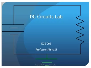
DC Circuits Lab ECE 002 Professor Ahmadi
Outline Basic Components of a Circuit Series Circuit Parallel Circuit Ohm’s Law Lab Overview
Basic Circuit Components 1.5 V 1.5V We represent real electrical components with symbols A Battery… …can be represented with this symbol …called a “DC voltage source” • A DC Voltage Source • Provides Power for our circuit • Battery or Lab ‘power supply’ is an example • DC voltage is supplied across the two terminals • Its voltage is VOLTS (V)
Basic Circuit Components A Light Bulb…or any ‘device’… RΩ • A Resistor • Represents any device that requires power to operate • Could be a light bulb, your computer, a toaster, etc. • Each device has a certain amount of ‘resistance’, R, in • the unit called: OHMS (Ω) We represent real electrical components with symbols …can be represented with this symbol …called a “resistor”
Basic Circuit Components • The Ground • Represents 0 volts • We use it as a ‘reference’ voltage…to measure other • voltages against it • The ‘Earth’ is at 0 volts, so we call this ground We represent real electrical components with symbols The Earth… …can be represented with this symbol …called the “ground” symbol
Basic Circuit Components • The Diode • Controls the flow of current. • Has two ends called the anode and cathode. • Charges a ‘toll’ or voltage penalty of ~0.7V for passing through it. • If the anode voltage is not at least 0.7V, no current will flow to the cathode. We represent real electrical components with symbols A Tollbooth…or any ‘barrier’ …can be represented with this symbol …called a “diode”
Basic Circuit Components The diode is like a switch that takes ~0.7V to turn on Anode Cathode • The Diode Has Two Modes of Operation • Negative DC Voltage Source • When the Anode is at least ~0.7V. Replace the diode by a -0.7V DC Source. • Open Circuit • When the Anode is less than ~0.7V, the diode is an open circuit. This means no current can flow through it! = 0.7V =
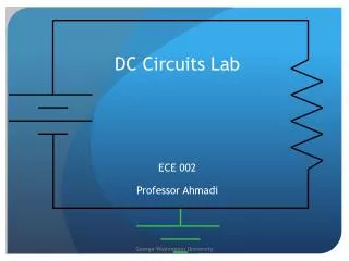
Building a Circuit… We wish to ‘power’ our flashlight’s light bulb… 1.5 V • We need a battery… • We need to attach the light bulb to the battery… • We use wires to connect the light bulb to the battery… Instead…let's represent the real components with their symbols
Building a Circuit… Replace the battery with a ‘DC Voltage Source’ symbol 1.5 V 1.5V creating a schematic • Replace the light bulb with a ‘Resistor’ symbol .5Ω • Mark the symbol’s values (V=, R=, etc.) Since this “node” is at GND (OV) this node must be 1.5Volts higher • Add the Ground reference 0V Instead…let's represent the real components with their symbols
Analyzing the Circuit…using Ohm’s Law Ohm’s Law (V=IR) ->Describes the relationship between the voltage (V), current (I), and resistance (R) in a circuit 1.5V • When we attach the resistor to the DC voltage source, current begins to flow • How much current will flow? .5KΩ • Using Ohm’s Law, we can determine how much current is flowing through our circuit 0V
Analyzing the Circuit…using Ohm’s Law Use Ohm’s Law: V = I x R 1.5V = Ix .5K Ω Solve for I: I = 1.5V / .5 KΩ = 3 mA I = 3 mA 1.5V • How much current will flow? .5KΩ 0V So, 3 mA will flow through the .5kΩ resistor, when 1.5 Volts are across it
Resistors in Series 1.5V • Resistors connected by only 1 terminal, back-to-back, are considered to be in ‘series’ R1 = .5KΩ • We can replace the two series resistors with 1 single resistor, we call Req • The value of Req is the SUM of R1 & R2: Req=R1+R2=.5K Ω + .5K Ω = 1KΩ Req = 1KΩ R2 = .5KΩ 0V
Resistors in Series Use Ohm’s Law: V = I x Req 1.5V = Ix 1K Ω Solve for I: I = 1.5V / 1K Ω = 1.5 mA I = 1.5 mA 1.5V • Now we can find the current through the circuit using Ohm’s Law Req = 1KΩ 0V The bigger the resistance in the circuit, the harder it is for current to flow
Resistors in Series I = 1.5 mA 1.5V • Back to our original series circuit, with R1 and R2 • The current is the SAME through each resistor R1 = .5KΩ • Current flows like water through the circuit, notice how the 1.5 mA ‘stream of current’ flows through both resistors equally R2 = .5KΩ • Ohm’s Law shows us voltage across each resistor: V(R1) = 1.5mA x .5K Ω = .75V V(R2) = 1.5mA x .5K Ω = .75V 0V
Resistors in Parallel 1.5V Req = .25K Ω • Resistors connected at 2 terminals, sharing the same node on each side, are considered to be in ‘parallel’ • Unlike before, we cannot just add them. We must add their inverses to find Req: R1 = .5KΩ R2 = .5KΩ 0V
Resistors in Parallel Use Ohm’s Law, we find the current through Req: V = I x Req 1.5V = Ix .25K Ω Solve for I: I = 1.5V / .25KΩ = 6 mA I = 6 mA 1.5V • This is the equivalent circuit Req = .25KΩ 0V The smaller the resistance in the circuit, the easier it is for current to flow
Resistors in Parallel 1.5V • Back to our original series circuit, with R1 and R2 • The current is NOT the SAME through all parts of the circuit • Current flows like water through the circuit, notice how the 6 mA ‘stream of current’ splits to flow into the two resistors R1 = .5KΩ R2 = .5KΩ • The Voltage across each resistor is equal when they are in parallel 0V
Resistors in Parallel I = 3 mA I = 3 mA I = 6 mA 1.5V • The voltage is 1.5 V across each resistor • Ohm’s Law tells us the current through each: I(R1)=V/R= 1.5V /.5KΩ = 3mA I(R2)=V/R= 1.5V /.5KΩ = 3mA • The 6mA of current has split down the two legs of our circuit • It split equally between the two legs, because the resistors have the same value R1 = .5KΩ R2 = .5KΩ 0V The current will split differently if the resistors are not equal…
Resistors in Parallel Use Ohm’s Law, we find the current through Req: V = I x Req 1.5V = Ix .25K Ω Solve for I: I = 1.5V / .25K Ω = 6 mA I = 6 mA 1.5V • This is the equivalent circuit Req = .25KΩ 0V The smaller the resistance in the circuit, the easier it is for current to flow
Including a Diode First, is the anode potential at least 0.7V? 1.5V • Steps to Analyze the Circuit Anode = 1.5V • Yes, it is at 1.5V. So, replace the diode with a -0.7V DC Source. R = .5KΩ 0V
Including a Diode Voltage sources in series can be combined. 1.5V • Steps to Analyze the Circuit 0.7V • 1.5V + (-0.7)V = 0.8V • Use that 0.8V value as the V in Ohm’s Law! R = .5KΩ 0V
Including a Diode Now, how much current will flow through R? I = 1.6 mA 0.8V • Steps to Analyze the Circuit • Use Ohm’s Law: V = I x R 0.8V = Ix .5K Ω Solve for I: I = 0.8V / .5 Ω = 1.6 mA R = .5KΩ 0V
Including a Diode The Voltage on the Left (From the DC Source) Should equal the Voltage Drops on the Right. 1.5V • Check Your Answer 0.7V Use Ohm’s Law For the Resistor: VR= I x R 0.8V= 1.6mA x .5K Ω For the Diode: VD = 0.7V Add the Voltage Drops: VR +VD = 0.8V+0.7V= 1.5V This matches our voltage source…YAY! R = .5KΩ 0V
Including a Diode First, is the anode potential at least 0.7V? I = 0 Amps 0.5V • Steps to Analyze the Circuit Anode = 0.5V R = .5KΩ • No, it is at 0.5V. Therefore, no current can flow through the resistor. 0V
In Summary… Ohm’s Law: V=IR Describes the relationship between the voltage (V), current (I), and resistance (R) in a circuit Current is equal through two resistors in series Voltage drops across each resistor Req = R1 + R2 + . . . Voltage is equal across two resistors in parallel Current splits through branches of parallel circuits 1/Req = 1/R1 + 1/R2
In Summary… Diodes There is a voltage cost associated with every diode. Current will only flow through the diode if the voltage at the anode is ≥ to that cost.
In Lab Today You will build series circuits Build parallel circuits Work with a breadboard Verify Ohm’s Law by measuring voltage using a multimeter And yes, there is HW!