Download
1 / 25
250 likes | 343 Vues
Detailed report on the development process of low voltage power supply subsystem for vehicle control. Includes efficiency, recommendations for production, and integration plans for various converter assemblies.

E N D
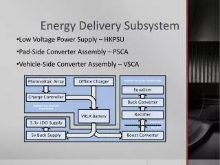
Energy Delivery Subsystem Low Voltage Power Supply – HKPSU Pad-Side Converter Assembly – PSCA Vehicle-Side Converter Assembly – VSCA
RVP Circuit 3.3 volt LDO 5 volt converter • Provides 3.3v and 5v to control system loads • 5 volt 2.2 amp buck converter based on LTC1938 • 3.3 volt 1 amp linear regulator • Incorporates reverse voltage protection on input
Final revision of prototype tested to required performance • Peak efficiency of prototype 5 volt converter is 89.5% • Recommendations for production include : • Redesign to eliminate LDO losses if cost-effective • Eventual integration into CSA
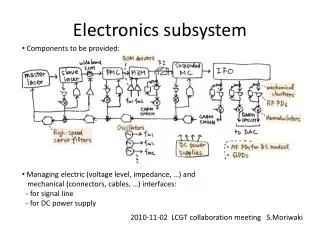
Input & Output Filter Capacitors RVP Circuit Switching FETs Undervoltage Detector Main Inductor PWM Controller • Boost supply to convert battery voltage to 20 volts at pad contacts • 20 volt 5 amp boost converter based on LTC3786 operating at 400kHz • Incorporates undervoltage sensing circuit for interface with the CSA • Incorporates reverse voltage protection and output isolation
Prototype was able to meet output and UVSENSE requirements • Significant inductor core losses required fan cooling for sustained loads • Peak efficiency of prototype converter is 92.5% versus expected 95.6% • Version 3 layout includes changes to minimize these losses
Recommendations for production include: • Adoption of v3 layout revision • Use of Dow SE4486CV or similar for heat sink bonding
Buck Converter Circuit CT microcontroller Equalizer Circuit FET Rectifier Bridge Isolation Switch • Converts 20 volt pad potential to 12.6 volts to charge vehicle battery • 12.6 volt buck converter based on LTC3741 operating at 500kHz • Incorporates low-loss FET rectifier on input • Incorporates cell equalizer circuit • Includes microcontroller for supervisory tasks required as a Li-poly charger
Core buck converter: • Adjustable for prototyping 12.2-12.8 volt with 4.6-7.5 amp limit • Cell equalizer: • Rated for 3 watts per cell • Connector-compatible with specified battery harness • Charge Termination microcontroller: • Mediates enable signal from vehicle • Monitors input voltage, battery temperature, output current • Suspends or terminates charge based on operating conditions and time
Core buck converter: • Not stabilized for required output current • Layout revision and component re-evaluation is necessary • Ground isolation • Impact of low gate charge on stability • Re-routing of control and feedback networks • Cell equalizer: • Tested to maximum loading without issue • May be made larger if greater imbalance correction per cycle is req’d • Charge Termination microcontroller: • Demonstration hardware and code developed for incremental testing • Proper charge suspend and termination routines tested with success • A controller with more I/O pins may be used to allow better interfacing • May be moved to SMT to reduce cost and size
Control System Hardware • Vehicle-Side • Landing Illuminator Assembly • Visible Red Lamps • Near-Infrared Lamps Pad-Side Purchased Components GPS Receiver XBEE radio CMUcam System Control System Assembly (CSA)
GPS Receiver • SFE Venus-GPS module based on the SkyTraqVENUS634FLPx • External antenna connection and 3.3v UART • $49.95 retail
XBEE Radio • 50 mW Series2 XBEE-Pro radio • Outdoor range up to 1 mile (approx) • Supports PTP, PTMP, Mesh network modes • $44.95 Retail
Camera System • CMUcam 2 Motion-tracking camera • Locates contiguous regions of color selected by user-defined bins • Tracks color blobs at up to 50 FPS • $179 Retail • Not purchased due to availability issues • Camera Shutter • Required to prevent sensor damage • May be modified to incorporate a filter wheel
Control System Assembly (CSA) • Provides USB translation for GPS, radio, camera UARTs • Incorporates USB hub for single-cable interface to host computer • Includes Atmel AT90USB162 microcontroller for general purpose I/O • Reading battery status at PSCA • Enable PSCA or camera • Operate camera shutter motor
GPIO Microcontroller Camera Interface GPS Interface Radio Interface USB Hub • Control System Assembly (CSA) • Provides USB translation for GPS, radio, camera UARTs • Incorporates USB hub for single-cable interface to host computer • Includes Atmel AT90USB162 microcontroller for general purpose I/O • Reading battery status at PSCA • Enable PSCA or camera • Operate camera shutter motor
Early considerations included the option of eliminating external computer • A single microcontroller could be used for interface and control • Early version recommended for further development • Current USB system is more expensive, but modular • Allows components and layouts to be proofed independent of embedded host controller code
Design Performance: • USB hub and GPS/Radio interfaces tested to meet req’s • No camera purchased or tested, but interface HW works • GPIO controller damaged in handling • Basic control routines programmed for demo board w/success • No longer able to develop USB interface code • Final layout shares same functionality as demo modules
Landing Illuminator Assembly (LIA) • Mounts to VSCA and provides an LED beacon for craft location by camera • Adjustable boost converter based on LTC1373 • Constant-voltage design is simple, but requires lamp consideration • Design allows for better efficiency, flexibility over series regulators • Flexibility required due to evaluation of different lamp types
Lamp types and concerns • Imaging routines must adapt to sky conditions • During dusk or low-contrast, moderate illumination conditions: • Vehicle silhouette may be difficult to track • Remaining sky light inhibits illuminator effectiveness • Careful selection of emitter type may be beneficial • Both 625 nm and 850 nm lamps were considered • Initial experiments suggest the use of NIR lamps with optical filter • Sensor specs suggest use of filter for daylight imaging • Shutter assembly can be modified to incorporate filters • Not tested with CMUcam