Multi Cycle CPU
Multi Cycle CPU. Previously: built a Single Cycle CPU. Today: Exceptions Multi-cycle CPU; Microprogramming. Mid-term Review Discussion Session. Peterson Hall 104 Tue: 2-3 pm Tue: 3-4 pm. The Story so far:. Instruction Set Architectures Performance issues

Multi Cycle CPU
E N D
Presentation Transcript
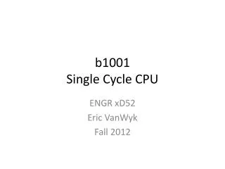
Multi Cycle CPU • Previously: built a Single Cycle CPU. • Today: • Exceptions • Multi-cycle CPU; • Microprogramming Tarun Soni, Summer ‘03
Mid-term Review Discussion Session • Peterson Hall 104 • Tue: 2-3 pm • Tue: 3-4 pm Tarun Soni, Summer ‘03
The Story so far: • Instruction Set Architectures • Performance issues • 2s complement, Addition, Subtraction • Multiplication, Division, Floating Point numbers • ALUs • Single Cycle CPU • Exceptions • Multicycle CPU: datapath; control • Microprogramming Tarun Soni, Summer ‘03
Alternative Architectures • Design alternative: • provide more powerful operations • goal is to reduce number of instructions executed • danger is a slower cycle time and/or a higher CPI • Sometimes referred to as “RISC vs. CISC” • virtually all new instruction sets since 1982 have been RISC • VAX: minimize code size, make assembly language easy instructions from 1 to 54 bytes long! • We’ll look at Pentium, UltraSparc and JVM Tarun Soni, Summer ‘03
Pentium Tarun Soni, Summer ‘03
Java VM • Most instr one byte • ADD • POP • One byte arg • ILOAD IND8 • BIPUSH CON8 • Two byte arg • SIPUSH CON16 • IF_ICMPEQ OFFSET16 • Type = int, signed int etc. Tarun Soni, Summer ‘03
UltraSparc Tarun Soni, Summer ‘03
Exceptions or Oops! Tarun Soni, Summer ‘03
Exceptions • There are two sources of non-sequential control flow in a processor • explicit branch and jump instructions • exceptions • Branches are synchronous and deterministic • Exceptions are typically asynchronous and non-deterministic • Guess which is more difficult to handle? • arithmetic overflow • divide by zero • I/O device signals completion to CPU • user program invokes the OS • memory parity error • illegal instruction • timer signal • exceptions as any unexpected change in control flow • interrupts as any externally-caused exception • Literature is not consistent Tarun Soni, Summer ‘03
Exceptions • The machine we’ve been designing in class can generate two types of exceptions. • arithmetic overflow • illegal instruction • On an exception, we need to • save the PC (invisible to user code) • record the nature of the exception/interrupt • transfer control to OS System Exception Handler user program Exception: return from exception Tarun Soni, Summer ‘03
Exceptions • Interrupts • caused by external events • asynchronous to program execution • may be handled between instructions • simply suspend and resume user program • Traps/Exceptions • caused by internal events • exceptional conditions (overflow) • errors (parity) • faults (non-resident page) • synchronous to program execution • condition must be remedied by the handler • instruction may be retried or simulated and program continued or program may be aborted • MIPS architecture defines the instruction as having no effect if the instruction causes an exception. • When we get to virtual memory we will see that certain classes of exceptions must prevent the instruction from changing the machine state. • This aspect of handling exceptions becomes complex and potentially limits performance => why it is hard Tarun Soni, Summer ‘03
handler code iv_base cause Exceptions Addressing the Exception Handler • Traditional Approach: Interupt Vector • PC <- MEM[ IV_base + cause || 00] • 370, 68000, Vax, 80x86, . . . • RISC Handler Table • PC <– IT_base + cause || 0000 • saves state and jumps • Sparc, PA, M88K, . . . • MIPS Approach: fixed entry • PC <– EXC_addr • Actually very small table • RESET entry • TLB • other handler entry code iv_base cause Tarun Soni, Summer ‘03
Exceptions Saving State • Push it onto the stack • Vax, 68k, 80x86 • Save it in special registers • MIPS EPC, BadVaddr, Status, Cause • Shadow Registers • M88k • Save state in a shadow of the internal pipeline registers Significant component of “interrupt response time” Tarun Soni, Summer ‘03
Exceptions • For our MIPS-subset architecture, we will add two registers: • EPC: a 32-bit register to hold the user’s PC • Cause: A register to record the cause of the exception • we’ll assume undefined inst = 0, overflow = 1 • We will also add three control signals: • EPCWrite (will need to be able to subtract 4 from PC) • CauseWrite • IntCause • We will extend PCSource multiplexor to be able to latch the interrupt handler address into the PC. Tarun Soni, Summer ‘03
Instruction<31:0> Inst Memory <0:15> <21:25> <16:20> <11:15> Adr Rs Rt Rd Imm16 RegDst nPC_sel ALUctr MemWr MemtoReg Equal Rt Rd 0 1 Rs Rt 4 RegWr 5 5 5 busA Adder Rw Ra Rb = 00 busW 32 32 32-bit Registers ALU 0 32 Mux busB 32 0 PC PCWrite EPCWrite 32 Mux Mux Clk 32 Adder sub 4 WrEn Adr 1 PC EPC Clk 1 Interrupt Handler Address Data In Extender Data Memory PC Ext imm16 32 16 imm16 PCSource Clk ExtOp ALUSrc Exceptions CauseWrite Cause IntCause Tarun Soni, Summer ‘03
Exceptions: Creating a “Control line” • Regs: • EPC: • Cause: • control signals: • EPCWrite (subtract 4 from PC) • CauseWrite • IntCause Instruction<31:0> Inst Memory <21:25> <21:25> <16:20> <11:15> <0:15> Adr Op Fun Rt Rs Rd Imm16 Control Exception Signals ALUctr nPC_sel MemWr MemtoReg ALUSrc RegWr RegDst ExtOp Equal DATA PATH Tarun Soni, Summer ‘03
ALU PC Clk Exceptions: Creating the data path • Regs: • EPC: • Cause: • control signals: • EPCWrite (subtract 4 from PC) • CauseWrite • IntCause • Extend PCSource MUX to include jump address from int-table Ideal Instruction Memory Instruction Rd Rs Rt Imm 5 5 5 16 Instruction Address A Data Address 32 Rw Ra Rb 32 Ideal Data Memory 32 32 32-bit Registers Next Address Data In B Clk Clk 32 Tarun Soni, Summer ‘03
CPU Multi Cycle CPU Tarun Soni, Summer ‘03
Control Datapath CPU The Big Picture: Where are We Now? • The Five Classic Components of a Computer • Datapath Design, then Control Design Processor Input Memory Output Tarun Soni, Summer ‘03
Recap: Processor Design is a Process • Bottom-up • assemble components in target technology to establish critical timing • Top-down • specify component behavior from high-level requirements • Iterative refinement • establish partial solution, expand and improve Instruction Set Architecture => processor datapath control Reg. File Mux ALU Reg Mem Decoder Sequencer Cells Gates Tarun Soni, Summer ‘03
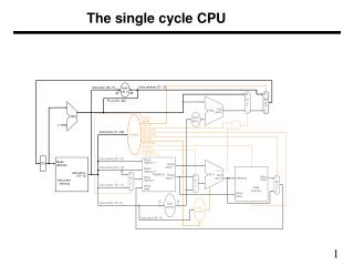
Instruction Fetch Instruction Decode Operand Fetch Execute Result Store Next Instruction CPU: The single cycle Execute Decode Fetch Fetch Store Next Execute an entire instruction ° Design hardware for each of these steps!!! Tarun Soni, Summer ‘03
. . . . . . . . . . . . CPU: Clocking Clk Setup Hold Setup Hold Don’t Care • All storage elements are clocked by the same clock edge Tarun Soni, Summer ‘03
. . . . . . op<5> op<5> op<5> op<5> op<5> op<5> . . . . . . <0> <0> <0> <0> <0> op<0> R-type ori lw sw beq jump CPU: Main Control PLA Implementation of the Main Control RegWrite ALUSrc RegDst MemtoReg MemWrite Branch Jump ExtOp ALUop<2> ALUop<1> ALUop<0> Tarun Soni, Summer ‘03
CPU: Main Control OPcode Control Logic / Store (PLA, ROM) Decode microinstruction Conditions Control Points Instruction Datapath • In our single-cycle processor, each instruction is realized by exactly one control command or “microinstruction” • in general, the controller is a finite state machine • microinstruction can also control sequencing (see later) Tarun Soni, Summer ‘03
CPU: Abstract View of a single cycle processor Main Control op ALU control fun ALUSrc Equal ExtOp MemRd MemWr MemWr RegDst RegWr nPC_sel ALUctr Reg. Wrt ALU Register Fetch Ext Mem Access PC Instruction Fetch Next PC Result Store Data Mem • looks like a FSM with PC as state Tarun Soni, Summer ‘03
CPU: Why is a CPI=1 processor bad? Arithmetic & Logical PC Inst Memory Reg File ALU setup mux mux Load PC Inst Memory Reg File ALU Data Mem setup mux mux Critical Path Store PC Inst Memory Reg File ALU Data Mem mux Branch PC Inst Memory Reg File cmp mux • Long Cycle Time • All instructions take as much time as the slowest • Real memory is not so nice as our idealized memory • cannot always get the job done in one (short) cycle Tarun Soni, Summer ‘03
CPU: Why is a CPI=1 processor bad? Goal: balance amount of work done each cycle. • Load needs 5 cycles • Store and R-type need 4 • beq needs 3 Tarun Soni, Summer ‘03
CPU: Reducing Cycle Time • Cut combinational dependency graph and insert register / latch • Do same work in two fast cycles, rather than one slow one storage element storage element Acyclic Combinational Logic (A) Acyclic Combinational Logic => storage element Acyclic Combinational Logic (B) storage element storage element Tarun Soni, Summer ‘03
CPU: Building blocks CarryIn • Adder • MUX • ALU A 32 Sum Adder 32 B Carry 32 Select A 32 MUX Y 32 B 32 OP A 32 Result ALU 32 B 32 Tarun Soni, Summer ‘03
CarryIn A[31..0] 32 32 Sum[31..0] Adder 32 Select B[31..0] Carry A 32 MUX Y A[63..32] CarryIn 32 32 B 32 Sum[63..32] Adder 32 OP B[63..32] Carry 32 CPU: Building blocks • Building a 64-bit adder from 2x32-bit adders • Speed of addition? • For one ADD? • For consecutive ADDS? Tarun Soni, Summer ‘03
Multicycle CPU: Individual operations • Next address logic • PC <= branch ? PC + offset : PC + 4 • Instruction Fetch • InstructionReg <= Mem[PC] • Register Access • A <= R[rs] • ALU operation • R <= A + B Control MemRd MemWr MemWr RegDst RegWr nPC_sel ALUctr ALUSrc ExtOp Reg. File Exec Operand Fetch Mem Access Instruction Fetch PC Next PC Result Store Data Mem Tarun Soni, Summer ‘03
Multicycle CPU: Partitioning Time • Five execution steps (some instructions use fewer) • IF: Instruction Fetch • ID: Instruction Decode (& register fetch & add PC+immed) • EX: Execute • Mem: Memory access • WB: Write-Back into registers IF ID EX Mem WB Tarun Soni, Summer ‘03
Multicycle CPU: Steps Note: Reuse of ALU IF ID Ex Mem WB Tarun Soni, Summer ‘03
Multicycle CPU Partitioning the CPI=1 Datapath • Add registers between smallest steps MemRd MemWr MemWr RegDst RegWr nPC_sel ALUSrc ExtOp ALUctr Reg. File Exec Operand Fetch Mem Access Instruction Fetch PC Next PC Result Store Data Mem Tarun Soni, Summer ‘03
Ifetch Reg Exec Mem Wr Ifetch Reg Exec Mem Ifetch Multicycle CPU Cycle 1 Cycle 2 Clk Single Cycle Implementation: Load Store Waste Cycle 1 Cycle 2 Cycle 3 Cycle 4 Cycle 5 Cycle 6 Cycle 7 Cycle 8 Cycle 9 Cycle 10 Clk Multiple Cycle Implementation: Load Store R-type Tarun Soni, Summer ‘03
Multicycle CPU: Instruction Types Tarun Soni, Summer ‘03
Multicycle CPU: Sharing Hardware IR <- Mem[PC] A <- R[rs]; B<– R[rt] S <– A + B S <– A or ZX S <– A + SX S <– A + SX M <– Mem[S] Mem[S] <- B R[rd] <– S; PC <– PC+4; R[rt] <– S; PC <– PC+4; R[rd] <– M; PC <– PC+4; PC <– PC+4; PC < PC+4; PC < PC+SX; • Example: memory is used twice, at different times • Ave mem access per inst = 1 + Flw + Fsw ~ 1.3 • if CPI is 4.8, imem utilization = 1/4.8, dmem =0.3/4.8 • We could reduce HW without hurting performance • extra control Tarun Soni, Summer ‘03
Multicycle CPU: Sharing Functional Units • Reuse: • ALU • Memory • Need more • Muxing • Control Single ALU, Common data and instruction memory datapath Tarun Soni, Summer ‘03
Multicycle CPU: Adding State Elements Since we reuse logic (e.g. ALU), we need to store results between states Need extra registers when: • signal is computed in one clock cycle and used in another, AND • the inputs to the combinational circuit can change before the signal is written into a state element. Tarun Soni, Summer ‘03
Multicycle CPU: Adding State Elements IF ID Ex Mem WB Tarun Soni, Summer ‘03
Multicycle CPU: The Full Multi-Cycle Implementation Tarun Soni, Summer ‘03
Cycle 1: Instruction Fetch Datapath: IR = Memory[PC], PC = PC + 4 (may be revised later) Control: IorD=0, MemRead=1, MemWr=0, IRwrite=1, ALUsrcA=0, etc Tarun Soni, Summer ‘03
Cycle 1: Instruction Decode A = Register[IR[25-21]] B = Register[IR[20-16]] ALUout = PC + (sign-extend (IR[15-0]) << 2) Tarun Soni, Summer ‘03
Cycle 2: Instruction Decode & RegFetch A = Reg[IR[25-21]] B = Reg[IR[20-16]] ALUout = PC + (sign-extend (IR[15-0]) << 2) We compute target address even though we don’t know if it will be used • Operation may not be branch • Even if it is, branch may not be taken Why? Everything up to this point must be instruction-independent, because we haven’t decoded the instruction. The ALU, the (incremented) PC, and the immed field are now all available Tarun Soni, Summer ‘03
Cycle 3 for beq: EXecute A ALU out B • In cycle 1, PC was incremented by 4 • In cycle 2, ALUout was set to branch target • This cycle, we conditionally reset PC: if (A==B) PC=ALUout Tarun Soni, Summer ‘03
Cycle 3: R-type Instruction • Cycle 3 (EXecute) ALUout = A op B • Cycle 4 (WriteBack) Reg[IR[15-11]] = ALUout R-type instruction is finished Tarun Soni, Summer ‘03
Cycle 3: R-type Instruction A B Cycle 3: ALUout = A op B Cycle 4:Reg[IR[15-11]] = ALUout Tarun Soni, Summer ‘03
Cycle 4: R-type Instruction A ALU out B Cycle 3: ALUout = A op B Cycle 4:Reg[IR[15-11]] = ALUout Tarun Soni, Summer ‘03
Multicycle CPU: The datapath MemToReg RegWr RegDst MemWr MemRd nPC_sel ALUctr ALUSrc ExtOp Equal Reg. File Ext ALU A Reg File R PC IR Next PC B Mem Access M Data Mem Instruction Fetch Result Store Operand Fetch • Extra Registers: • IR • A,B • R ( sometimes called S or ALUout) • M Tarun Soni, Summer ‘03
A S B M Multicycle CPU: The datapath inst Logical Register Transfers ADDU R[rd] <– R[rs] + R[rt]; PC <– PC + 4 • Logical Register Transfer • Physical Register Transfers inst Physical Register Transfers IR <– MEM[pc] ADDU A<– R[rs]; B <– R[rt] S <– A + B R[rd] <– S; PC <– PC + 4 Equal Reg. File Reg File Exec IR PC Next PC Inst. Mem Mem Access Data Mem Tarun Soni, Summer ‘03