Download
1 / 25
250 likes | 272 Vues
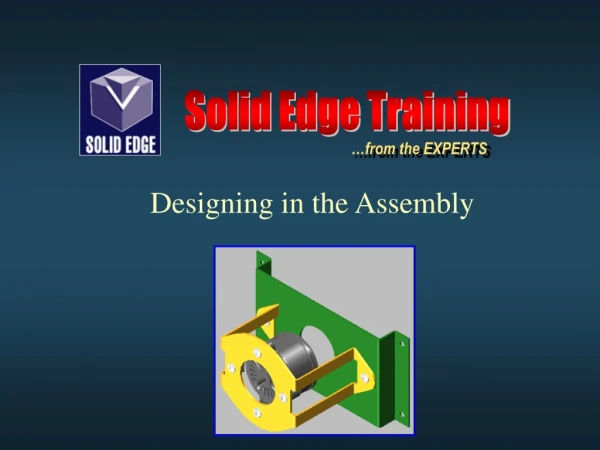
Learn how to design in the assembly using Solid Edge software. Topics include inter-part linking, inter-part copy, and assembly reference planes.

E N D
Solid Edge Training …from the EXPERTS Designing in the Assembly
Objectives • Create in Place • Inter-Part Linking • Inter-Part Copy • Linking to Sketches • Assembly Reference Planes • Multi-Part Cutout • Pasting Variables • Inter-Part Manager
Why Model in the Assembly? The benefit gained from modeling within the assembly... • existing parts can constantly be referenced to assure proper fit and alignment to the new part being modeled.
Create In-Place • Must be in Assembly environment • Create In-Place button located on Parts Library tab of EdgeBar
Create In-Place • Clicking Create In-Place button displays the Create In-Place dialog box • the following input is required... For selecting a template for the new part file (.par or .psm) Type in new file name Select directory for new file to reside
Create In-Place • Input required (continued)... Places new part at center of assembly file Positions new part from face or edge of existing part New part position is offset from the assembly file origin… By keypoint-use keypoint from an existing part By value-position by typing in values in the X,Y,Z
Inter-Part Associativity • Establishes associative linking between mating parts • Must use create In-Place method of new part construction • Must explicitly indicate to Solid Edge that inter-part relationships are desired by accessing desired options on the Inter-Part dialog box
Inter-Part Linking • To access…select Inter-Part tab on Tools>Options menu Copy geometry (i.e.; surfaces) from parent part to drive new part
Inter-Part Linking New Part thru Inter-Part Copy Inter-Part Copy New Part thru Inter-Part Copy follows after update Original Part Results Original Part - Modified How is this done? See next slide...
Inter-Part Linking Inter-Part Copy 2. Use Create In-Place to setup new part 3. Once in part environment select Inter-Part Copy…select desired faces Original Part in assembly - needs cover 1. Select this option Select faces
Inter-Part Linking • These faces are used to derive the • associative design parameters that • will drive the new part • The copied faces are used to… • draw the profile • control extents for thickness • hole location • The faces are driven by the original part in which they were copied. • If the original part changes the copied faces update driving the changes to the new part. Inter-Part Copy
Inter-Part Linking Inter-Part Copy Tip…the key to Inter-Part Copy is knowing what geometry to copy. Protrusion and Hole features made the new cover part.
Inter-Part Linking • To access…select Inter-Part tab on Tools>Options menu Copy assembly sketch geometry into a part file, if assembly sketch changes so does part(s)
Inter-Part Linking Note how parts show as associatively linked to part files Include from Assembly Sketches This sketch drawn on an assembly reference plane drives both parts Assembly
Inter-Part Linking Include from Assembly Sketches Before sketch modification After sketch modification
Inter-Part Linking • Inter-Part tab on Tools>Options menu (continued)... Allows you to use an assembly reference plane when constructing a new feature.
Inter-Part Linking Assembly Reference Planes in Feature • Permits use of an assembly reference plane to create a feature in a part file • Display of assembly reference plane(s) must be on • To select assembly reference plane in a part file you must use SHIFT select (hold shift key down to make reference plane selection). • Can be used for features including extents
Inter-Part Linking • Inter-Part tab on Tools>Options menu (continued)... Adds an associative cutout to multiple parts in an assembly
Inter-Part Linking Multi-Part Cutout Multi-Part Cutout Sketch on an assembly reference plane Parts selected for cutouts For Multi-Part Cutout button to be active the Multi-Part Cutout option must be enabled on the Tools>Options>Inter-Part (tab) dialog box. *Involved parts must be activated. Resulting Cutouts Assembly
Inter-Part Linking • Inter-Part tab on Tools>Options menu (continued)... Paste assembly variable into the Variable Table of other parts or assemblies
Inter-Part Linking Paste Link to Variable Table Permits pasting a variable created in the assembly variable table to corresponding part variables This assembly variable drives the holes in the two parts
Inter-Part Linking Assembly Variable Table Paste Link to Variable Table Create the assembly variable (example: Shaft_Hole) Copy the variable by right clicking for short cut menu Paste Link the variable to the appropriate part(s) file by right clicking for short cut menu Note…the Paste Link to Variable Table option must be selected on the Inter-Part Linking tab of the Tools>Options dialog box To see part changes in the assembly click the ‘Update All Links button... Part Variable Table
Inter-Part Manager • Inter-Part Manager is a dialog interface that permits display and management of inter-part relationships in an assembly
Inter-Part Manager • Symbols used to indicate status of links
Activities • Modeling Strategies – Page 171 • Inter-part assembly modeling • Assembly Manual – Page 303 • Using Sketches • Assembly Manual – Page 321 • Multi-Part cutout