Download
1 / 19
190 likes | 208 Vues
Status and first Results of the MEG Experiment. Jeanine Adam on behalf of the MEG Collaboration The New, the Rare and the Beautiful 7th January 2010 / University of Zurich. Introduction. MEG Detector. Data Taking. Goal Theory MEG Experiment. Goal.

E N D
Status and first Results of the MEG Experiment Jeanine Adam on behalf of the MEG Collaboration The New, the Rare and the Beautiful 7th January 2010 / University of Zurich
Introduction MEG Detector Data Taking • Goal • Theory • MEG Experiment Goal • Search for the lepton flavor violating decay • The goal is to reach a sensitivity of • Measured upper limits reached by other experiments: Zurich 2010 / Jeanine Adam / jeanine.adam@psi.ch
Introduction MEG Detector Data Taking • Goal • Theory • MEG Experiment Theory • Standard Model (SM) and - Oscillation: • MEG decay induced by neutrino oscillations with an estimated branching ratio of < 10 -40 (small neutrino masses) • Not verifiable by experimental methods! • Supersymmetry: • Supersymmetric theories predict branching ratios of ~10 -14 – 10 -12 • Just below the current experimental limit (1.2 × 10 -11)! • An observation of will reveal new physics beyond the SM! Zurich 2010 / Jeanine Adam / jeanine.adam@psi.ch
Introduction MEG Detector Data Taking • Goal • Theory • MEG Experiment Signature and Background • Signature of a event (decay at rest): • Emitted back-to-back • Each particle carries an energy equal to half of the muon mass (52.8 MeV) • Coincident in time • Background • Radiative muon decay: →e • Precise measurements of position, energy and timing both for photon and positron are necessary! • Accidental coincidence: →e + e.g. from AIF Zurich 2010 / Jeanine Adam / jeanine.adam@psi.ch
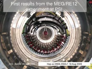
Introduction MEG Detector Data Taking • Goal • Theory • MEG Experiment MEG Experiment • International collaboration of ~80 physicists • MEG is located at the Paul Scherrer Institute (PSI): • 590 MeV proton ring cyclotron facility • 2.2 mA proton current • E5 beam channel: Surface of 28 MeV/c • Continuous beam Zurich 2010 / Jeanine Adam / jeanine.adam@psi.ch
Introduction MEG Detector Data Taking • Beam and Target • Photon Detector • Positron Spectrometer MEG Detector • Photon: Liquid xenon scintillation detector (position, timing, energy) • Positron: COBRA positron spectrometer (position, timing, energy) Zurich 2010 / Jeanine Adam / jeanine.adam@psi.ch
Introduction MEG Detector Data Taking • Beam and Target • Photon Detector • Positron Spectrometer Beam and Target • Beam • E5 beam channel • Wien filter ( / separation) • Superconducting beam transport solenoid (BTS) with degrader • Stopping rate of 3 × 10 7/sec • Target • 205 m thick polyethylene foil clamped between a ROHACELL frame • Slanted angle of 20.5° • Holes (r=5mm) to check vertex reconstruction BTS target E / Wien filter MEG detector quadrupole magnets 590 MeV proton beam Zurich 2010 / Jeanine Adam / jeanine.adam@psi.ch
Introduction MEG Detector Data Taking • Beam and Target • Photon Detector • Positron Spectrometer Photon Detector • Photons are detected with the world’s largest liquid xenon detector • Filled with 900 liter of LXe (T=161-165 K) • Scintillation light is picked up by 846 PMTs surrounding the detector • High purity at sub-ppm level to avoid scintillation light absorption due to impurities (water, oxygen) Zurich 2010 / Jeanine Adam / jeanine.adam@psi.ch
Introduction MEG Detector Data Taking • Beam and Target • Photon Detector • Positron Spectrometer Positron Spectrometer • The MEG positron spectrometer consists of a specially designed superconducting magnet COBRA, a drift chamber system and timing counters • The spectrometer provide momentum, track and timing information about the positron Zurich 2010 / Jeanine Adam / jeanine.adam@psi.ch
Introduction MEG Detector Data Taking • Beam and Target • Photon Detector • Positron Spectrometer Positron Spectrometer: COBRA • COBRA is composed of a superconducting main magnet and two normal conducting compensation coils: • Main magnet: Composed of 5 superconducting coils with different radii → gradient magnetic field (B = 0.49 – 1.27 Tesla) • Compensation Coils: Reduce magnetic field around the photon detector Zurich 2010 / Jeanine Adam / jeanine.adam@psi.ch
Introduction MEG Detector Data Taking • Beam and Target • Photon Detector • Positron Spectrometer Positron Spectrometer: COBRA Advantages • Positrons emitted close to 90° • COnstant Bending RAdius Zurich 2010 / Jeanine Adam / jeanine.adam@psi.ch
Introduction MEG Detector Data Taking • Beam and Target • Photon Detector • Positron Spectrometer Positron Spectrometer: Drift Chamber System • MEG drift chamber system: • 16 modules aligned radially to the beam axis • Each module consists of two wire planes shifted against each other • Low-material construction: • Cathodes consist of 12.5 m thick Kapton foils with 250 nm aluminium deposition • Open frame construction • Operated with a He:C2H6 (50:50) gas mixture Zurich 2010 / Jeanine Adam / jeanine.adam@psi.ch
Introduction MEG Detector Data Taking • Beam and Target • Photon Detector • Positron Spectrometer Positron Spectrometer: Timing Counter • The MEG timing counter consists of two scintillator timing counter arrays placed at each end of the spectrometer each with a 2-layer construction: • Phi-Counter: • Plastic scintillator bars along beam axis • Read out by PMTs at both sides • Positron timing measurement • Z-Counter: • Scintillation fibers • Read out by APDs • Additional trigger information scintillating fibers with APDs scintillation bars with PMTs Zurich 2010 / Jeanine Adam / jeanine.adam@psi.ch
Introduction MEG Detector Data Taking • Run 2008 • Results 2008 • Run 2009 Data Taking • Commissioning run 2007: • All detector components assembled • Calibrations, trigger tuning • Test physics run (1 – 2 days) • Run 2008: • Shutdown period: Solve problems appeared during 2007 • May – Aug 2008: Calibrations • Sep – Dec 2008: Physics data taking ( ~ 3 months) • Remark: • PSI accelerator shutdown from Christmas to mid of April → no beam! • Another experiment is located in the E5 area → beam time is split Zurich 2010 / Jeanine Adam / jeanine.adam@psi.ch
Introduction MEG Detector Data Taking • Run 2008 • Results 2008 • Run 2009 MEG Detector Resolutions in 2008 • Positron Energy: • Resolution function: triple Gaussian (core + 2 tail components) • Core: 374 keV (60%)Tails: 1.06 MeV (33%) / 2.00 MeV (7%) • Photon Energy: • Asymmetric with low-energy tail • E/E = (5.8 ± 0.35) % FWHM with a right tail of R = (2.0 ± 0.15) % • Positron – Photon Timing: • te = (152 ± 16) ps • Positron – Photon Angles: • e ~ 21 mrad • e ~ 14 mrad Zurich 2010 / Jeanine Adam / jeanine.adam@psi.ch
Introduction MEG Detector Data Taking • Run 2008 • Results 2008 • Run 2009 Blind Box & Likelihood Analysis Analysis Box Blind Box Pre-Selection Box • Pre-Selection Box: • Data reduction for analysis • Blind Box: • Written to separate data-stream • Not used to study background and optimize analysis • Analysis Box: • Maximum likelihood analysis basedon Feldmann – Cousins approach • The preliminary result from the first 3 months startup period of MEG 2008: 60 25 58 E [MeV] 20 56 54 52 15 50 48 10 46 44 5 42 0 40 16 32 34 36 22 24 26 28 30 18 20 T - Te [nsec] Source: arXiv:0908.2594v1 [hep-ex] “A limit for the decay from the MEG experiment” Zurich 2010 / Jeanine Adam / jeanine.adam@psi.ch
Run 2009 Jan – Aug 2009: Hardware improvements New printed circuit board (PCB) for the drift chambers→ DC high voltage problem solved Improvement of the LXe purification system→ higher light yield Installation of DRS4 chip→ ghost pulse problem solved, no/reduced temp. dep. September 2009: Detector assembling October 2009: Calibrations Nov – Dec 2009: Physics data taking ( ~ 2 months) Run 2009 stopped at 22 December 2009 Introduction MEG Detector Data Taking • Run 2008 • Results 2008 • Run 2009 Zurich 2010 / Jeanine Adam / jeanine.adam@psi.ch
Results 2009 The preliminary result from MEG run 2009: Introduction MEG Detector Data Taking • Run 2008 • Results 2008 • Run 2009 coming soon... Zurich 2010 / Jeanine Adam / jeanine.adam@psi.ch
Introduction MEG Detector Data Taking Summary and Prospects • The MEG experiment is searching for the LFV decayaiming a sensitivity of ~10 -13 • Physics data production started in Sep 2008 (physics runs in 2008/2009) • Data taken during the first startup period (3 months) of the MEG experiment in 2008 yielded an upper limit on the branching ratio of • MEG time schedule: • Hardware improvements (Jan – April 2010) • Assembling of all detector components / calibrations (May 2010) • Take physics data (June – Dec 2010, 2011) • MEG is expected to reach a sensitivity of ~10 -13 in a few years Zurich 2010 / Jeanine Adam / jeanine.adam@psi.ch