Reduction of Simple Distributed Loadings
220 likes | 335 Vues
Learn to determine equivalent forces for distributed loads, analyze load effects, design joints, understand moment of forces.

Reduction of Simple Distributed Loadings
E N D
Presentation Transcript
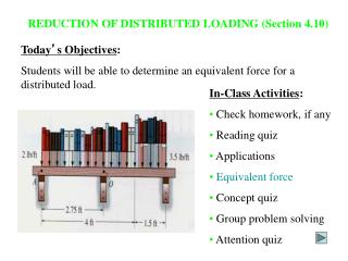
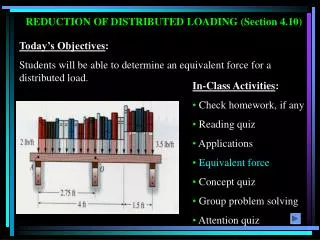
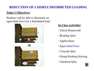
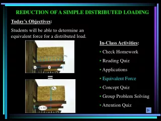
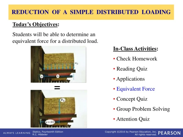
REDUCTION OF A SIMPLE DISTRIBUTED LOADING Today’s Objectives: Students will be able to determine an equivalent force for a distributed load. • In-Class Activities: • Check Homework • Reading Quiz • Applications • Equivalent Force • Concept Quiz • Group Problem Solving • Attention Quiz =
READING QUIZ 1. The resultant force (FR) due to a distributed load is equivalent to the _____ under the distributed loading curve, w = w(x). A) Centroid B) Arc length C) Area D) Volume Distributed load curve w x F R y 2. The line of action of the distributed load’s equivalent force passes through the ______ of the distributed load. A) Centroid B) Mid-point C) Left edge D) Right edge
APPLICATIONS There is a bundle (called a bunk) of 2” x 4” boards stored on a storage rack. This lumber places a distributed load (due to the weight of the wood) on the beams holding the bunk. To analyze the load’s effect on the steel beams, it is often helpful to reduce this distributed load to a single force. How would you do this?
APPLICATIONS (continued) The uniform wind pressure is acting on a triangular sign (shown in light brown). To be able to design the joint between the sign and the sign post, we need to determine a single equivalent resultant force and its location.
DISTRIBUTED LOADING In many situations, a surface area of a body is subjected to a distributed load. Such forces are caused by winds, fluids, or the weight of items on the body’s surface. We will analyze the most common case of a distributed pressure loading. This is a uniform load along one axis of a flat rectangular body. In such cases, w is a function of x and has units of force per length.
MAGNITUDE OF RESULTANT FORCE Consider an element of length dx. The force magnitude dF acting on it is given as dF = w(x) dx The net force on the beam is given by + FR = LdF = L w(x) dx = A Here A is the area under the loading curve w(x).
LOCATION OF THE RESULTANT FORCE The force dF will produce a moment of (x)(dF) about point O. The total moment about point O is given as + MRO = L x dF = L x w(x) dx Assuming that FR acts at , it will produce the moment about point O as + MRO = ( ) (FR) = L w(x) dx
LOCATION OF THE RESULTANT FORCE (continued) Comparing the last two equations, we get You will learn more detail later, but FR acts through a point “C,” which is called the geometric center or centroid of the area under the loading curve w(x).
EXAMPLE I Until you learn more about centroids, we will consider only rectangular and triangular loading diagrams whose centroids are well defined and shown on the inside back cover of your textbook. Look at the inside back cover of your textbook. You should find the rectangle and triangle cases. Finding the area of a rectangle and its centroid is easy! Note that triangle presents a bit of a challenge but still is pretty straightforward.
EXAMPLE I (continued) Now let’s complete the calculations to find the concentrated loads (which is a common name for the resultant of the distributed load). The rectangular load: FR = 400 10 = 4,000 lband = 5 ft. The triangular loading: FR = (0.5) (600) (6) = 1,800 N and = 6 – (1/3) 6 = 4 m. Please note that the centroid of a right triangle is at a distance one third the width of the triangle as measured from its base.
EXAMPLE II Given: The loading on the beam as shown. Find: The equivalent force and its location from point A. Plan: • The distributed loading can be divided into two parts. (one rectangular loading and one triangular loading). • 2) Find FR and its location for each of the distributed loads. • 3) Determine the overall FR of the point loadings and its location.
EXAMPLE II (continued) For the triangular loading of height 150 lb/ftand width 6ft, FR1= (0.5) (150) (6) = 450 lb and its line of action is at = (2/3)(6) = 4ftfrom A FR2 10 ft FR1 4 ft For the rectangular loading of height 150 lb/ftand width 8ft, FR2= (150) (8) = 1200 lb and its line of action is at = 6 + (1/2)(8) = 10ftfrom A
EXAMPLE II (continued) FR FR2 10 ft 8.36 ft FR1 4 ft The equivalent force and couple moment at A will be FR = 450 + 1200 = 1650 lb + MRA= 4 (450) +10(1200) = 13800 lbft Since (FR) has to equal MRA : 1650 =13800 Solve for to find the equivalent force’s location. = 8.36 ft from A.
CONCEPT QUIZ 1. What is the location of FR, i.e., the distance d? A) 2 m B) 3 m C) 4 m D) 5 m E) 6 m F R A B A B d 3 m 3 m 2. If F1 = 1 N, x1 = 1 m, F2 = 2 N and x2 = 2 m, what is the location of FR, i.e., the distance x. A) 1 m B) 1.33 m C) 1.5 m D) 1.67 m E) 2 m F x F x 1 F 2 R 2 x 1
GROUP PROBLEM SOLVING Given: The distributed loading on the beamas shown. Find: The equivalent force and couple moment acting at point O. Plan: • The distributed loading can be divided into two parts--two triangular loads. • 2) Find FR and its location for each of these distributed loads. • 3) Determine the overall FR of the point loadings and couple moment at point O.
GROUP PROBLEM SOLVING (continued) For the left triangular loading of height 6kN/m and width 7.5 m, FR1= (0.5) (6) (7.5) = 22.5 kN and its line of action is at = (2/3)(7.5) = 5 m from O FR1 9m FR2 5 m For the right triangular loading of height 6 kN/m and width 4.5 m, FR2 = (0.5) (6) (4.5) = 13.5 kN and its line of action is at = 7.5 + (1/3)(4.5) = 9m from O
GROUP PROBLEM SOLVING (continued) FR1 9m FR2 5 m The couple moment at point O will be + MRO= 500 + 5 (22.5) +9 (13.5) + 12 (15) = 914 kNm For the combined loading of the three forces, add them. FR = 22.5 + 13.5 + 15 = 51 kN
ATTENTION QUIZ F 100 N/m R 12 m x 2. x = __________. A) 3 m B) 4 m C) 6 m D) 8 m 1. FR = ____________ A) 12 N B) 100 N C) 600 N D) 1200 N
End of the Lecture Let Learning Continue