Download

1 / 15
150 likes | 343 Vues
COMP541 More on Verilog; Debouncing switches. Montek Singh Feb 15, 2012. First Topic. More Verilog…. Hierarchy. Always make your design modular easier to read and debug easier to reuse before you write even one line of Verilog… …draw a picture black boxes boxes within boxes.

E N D
COMP541More on Verilog;Debouncing switches Montek Singh Feb 15, 2012
First Topic • More Verilog…
Hierarchy • Always make your design modular • easier to read and debug • easier to reuse • before you write even one line of Verilog… • …draw a picture • black boxes • boxes within boxes module and3(input a, b, c, output y); assign y = a & b & c; endmodule module inv(input a, output y); assign y = ~a; endmodule module nand3(input a, b, c output y); wire n1; // internal signal and3 andgate(a, b, c, n1); // instance of and3 inv inverter(n1, y); // instance of inverter endmodule
Internal Variables • Internals = those that are not inputs/outputs • declare them as wire or reg • depending on whether they are combinational or state holding module fulladder(input a, b, cin, output s, cout); wire p, g; // internal assign p = a ^ b; assign g = a & b; assign s = p ^ cin; assign cout = g | (p & cin); endmodule
Bitwise Operators (we have used) module gates(input [3:0] a, b, output [3:0] y1, y2, y3, y4, y5); assign y1 = a & b; // AND assign y2 = a | b; // OR assign y3 = a ^ b; // XOR assign y4 = ~(a & b); // NAND assign y5 = ~(a | b); // NOR endmodule
Comments // single line comment /*…*/ multiline comment
Reduction Operators (&) module and8(input [7:0] a, output y); assign y = &a; // &a is much easier to write than // assign y = a[7] & a[6] & a[5] & a[4] & // a[3] & a[2] & a[1] & a[0]; endmodule
Reduction Operators (|, ~|, ~&, ^, ~^, ^~) • Several others (see online reference) • | = OR all the bits together • ~| = NOR all the bits together • ~& = NAND all the bits together • ^ = XOR all the bits together • ~^, ^~ = XNOR all the bits together
Operator Precedence Highest Lowest
Numbers • Format: N’Bvalue • N = number of bits, B = base • N’B is optional but recommended (default is decimal) • whenever in doubt, specify the # of bits
Bit Manipulations: splitting bits off module mux2_8(input [7:0] d0, d1, input s, output [7:0] y); mux2 lsbmux(d0[3:0], d1[3:0], s, y[3:0]); mux2 msbmux(d0[7:4], d1[7:4], s, y[7:4]); endmodule Verilog: Synthesis:
Bit Manipulations: packing bits assign y = {a[2:1], {3{b[0]}}, a[0], 6’b100_010}; // if y is a 12-bit signal, the above statement produces: y = a[2] a[1] b[0] b[0] b[0] a[0] 1 0 0 0 1 0 // underscores (_) are used for formatting only to make it easier to read. Verilog ignores them.
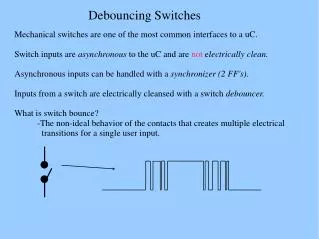
Debouncing switches What is switch bounce? Let’s solve it in class!
Switch bounce • Switches bounce or “chatter” • each press/release can bounce hundreds of times! • Let’s design a chatter-free switch for Friday’s lab!
Lab Preview: Buttons and Debouncing • Mechanical switches “bounce” • vibrations cause them to go to 1 and 0 a number of times • called “chatter” • hundreds of times! • We want to do 2 things: • “Debounce”: Any ideas? • Synchronize with clock • i.e., only need to look at it at the next +ve edge of clock • Ideas?