Multisim Tutorial
Multisim Tutorial. Basics of Schematic Capture [ Parts ] By James P. O’Rourke, D.Sc. Getting started with NI Multisim J.P.O’Rourke Loading Multisim : From Non ECE PC’s : (Click) Start |__Programs

Multisim Tutorial
E N D
Presentation Transcript
Multisim Tutorial Basics of Schematic Capture [ Parts ] By James P. O’Rourke, D.Sc.
Getting started with NI MultisimJ.P.O’Rourke • Loading Multisim: • From Non ECE PC’s : (Click) • Start • |__Programs • |___ Accessories • |___ Communications • |___ Remote Desktop • |___ ohm.ece.wpi.edu • From ECE PC’S : (Click) • Start • |___ ECELABS • |____ National Instruments • |____ Circuit Design Suite 11 • |____ Multisim
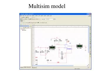
To get started with Schematic Capture, open a file called Multisim, under Programs as noted under the menu tree below. Note there is also a Getting Started Tutorial and complete documentation on the software under Documentation. • National Instruments • |_______ Circuit Design Suite 11 • |_________ Multisim • |_________ Documentation • When Multisim first launches, it opens with a Circuit Window called “Circuit 1”, noted on the top left of the screen and just below the bottom left of the Circuit window
About default software settings. If your default screen does not have the Virtual Toolbar present, the 2nd of the next two slides will explain how to generate it. Since the software is actually on the ECE department PC’s, default settings can be changed by the last person who used it. So if you find everything setup already, great and if not I have listed a procedure to obtain the desired format. ECE DEPARTMENT SERVERS with MULTISIM on them. 1. ohm 2. mho 3. amp These two servers are our latest additions and should have adequate capacity to handle our Remote Desktop needs.
The first step in Schematic Capture would be placing appropriate components in the Circuit Window. However, to assist in component placement the following are just some suggested settings to make NI Multisim easier to use. There are many additional optional setting under these Menus that may also be activated as the need arises. • Typical setup of the Circuit Window : • Click Options • |_____ Global Prop. • |_________ Save Create Security copy • Auto-backup • Save simulation data • There are other settings under the Global Prop. menus that may be • activated which control operations in the Circuit Window if you find • the default window, not to your liking.
Click Sheet Prop. • |______ Circuit • |____Net Names Check off • “ Show All “ • Again here, there are other menu tabs which controls operations on • the workspace that you may activate as the need arises. • Click View • |_____ Toolbars Virtual • Components • Standard • View • Main • Simulation switch • Simulation • Instruments • This is a basic set of the most used toolbars. Note activating all the Toolbars will take space away from the “Circuit Window”.
Working with the “Circuit Window : • If the “Toolbars” stack vertically above the Circuit Window, they may be spread out horizontally. To do this, move the mouse pointer to the right hand edge of the window to be moved and drag it to a new location, efficiently using all the available horizontal space. This will maximize the Circuit Window size for the “Toolbars “ that were chosen. • Closing the “Spreadsheet Window” below the circuit will also aid in maximizing the “Circuit Window”. When finished the Circuit Window should look similar to • figure 3. • The default window is generally called “Circuit 1 “ unless something was already saved using that name. If “Circuit 1” has been used then “Circuit 2” etc will be the default window. This might be a good time to rename this window under “Save As” so it doesn’t get accidentally saved as “Circuit 1”.
Getting started tutorials : • If you would like some “On Line Tutorials” instead of the tutorial that comes with the software, go to the “Web” and search for “ni.com”, main website( National Instruments – Test and Measurement). Click under the menu items “Support”. Under search, “all support resources”, type the Keyword “ multisim tutorial web cast”, then “go”. Click “ Circuit Design and Simulation : Educator and classroom resources”. This will allow access too many tutorials. • Now that we have gotten all this preliminary stuff out of the way, lets get started placing some components in the Circuit Window. • Go to the Virtual Toolbar, shown in figure 1 and click on the arrow to the right of the Battery symbol(Power Sources box). This will activate a drop down menu listing all the components available in the battery toolbox. The menu contains to types of grounds, a Digital Ground(called DGND) and the standard Analog Ground right below it. Digital Grounds are used with digital circuits and Analog Grounds with analog circuits. • Click on an Analog Ground symbol, labeled “Place Ground”, shown below. This will select a Ground that will follow your mouse movements around the Circuit Window till you locate it somewhere and then, left click the mouse to place it. Note that as soon as this is done the menu will automatically close. Don’t worry about it’s location since it can be moved later to any new location by holding down the left mouse button, moving to the new location and releasing. This method works for moving all components in the Circuit Window.
Some helpful suggestions: • If you need to select many items from a toolbox, having the window close automatically every time a component is selected can be annoying. This situation can be remedied by left clicking on the battery symbol itself. This will launch a toolbox on the Circuit Window that will stay there until you close it by left clicking on the little “x” in the upper right hand corner of the toolbox. This method of selecting components is generally preferred and will be used throughout this tutorial. • In Multisim the circuit design components are chosen from the Components and VirtualToolboxes, shown in figure 1. In most general designs and simulations, where no PC board layout is required, it is suggested that passive components be chosen from the Virtual Toolbox and the active components from the Components Toolbox. The choosing of Virtual passive components( resistors, capacitors and inductors) is suggested as a time saving feature since the component value is much easier to change by using this method. • This basically concludes the preliminary setup and use of the Circuit Window.