Download

1 / 21
240 likes | 563 Vues
Atomic Layer Deposition of Cerium Oxide for Solid Oxide F uel C ells. Rachel Essex , Rose- Hulman Institute of Technology Jorge Ivan Rossero Agudelo , Christos G. Takoudis , Gregory Jursich University of Illinois at Chicago.

E N D
Atomic Layer Deposition of Cerium Oxide for Solid Oxide Fuel Cells Rachel Essex, Rose-Hulman Institute of Technology Jorge Ivan RosseroAgudelo, Christos G. Takoudis, Gregory Jursich University of Illinois at Chicago
Benefits of Solid Oxide Fuel Cells as Alternate Power Source • No NOx, SOx, or hydrocarbon emissions • Reduced CO2 emissions • Fuel flexibility • Higher power density than batteries • High efficiency R.M., Ormerod: Chemical Society Reviews, 2003, 32, 17-28.
O2 (air) How a Solid Oxide Fuel Cell Works Cathode O-2 e- Electrolyte Anode CO2 and H2O H2 and CO • Solid oxide fuel cells components: • Cathode • Solid inorganic oxide electrolyte • Anode Fuel (hydrocarbon and steam or oxygen) R.M., Ormerod: Chemical Society Reviews, 2003, 32, 17-28.
The biggest setback for solid oxide fuel cell use is the high operating temperature • Operating temperature: 800-1000 ºC • Long heat up and cool down periods • Limited materials M. Cassir and E. Gourba: Annales de Chimie Science des Matériaux, 2001, 26, 49-58.
Decreasing Operating Temperatures • New materials with lower ion resistivity • Decreasing thickness can increase ion permeability • Thickness can be decreased using thin films M. Cassir and E. Gourba: Annales de Chimie Science des Matériaux, 2001, 26, 49-58.
Deposition of thin films • Physical vapor deposition -thin film deposition method by the condensation of a vaporized form a desired material onto surface • Purely physical process • High temperature vacuum evaporation or plasma sputter bombardment
Deposition of thin film (con’t) • Chemical vapor deposition -chemical process used to produce high-purity, high-performance solid materials • Metal organic chemical vapor deposition (MOCVD) • Atomic Layer Deposition (ALD)
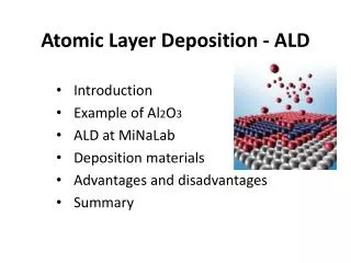
Atomic Layer Deposition • Each exposure to precursor saturates the surface with a monolayer • Purge of inert gas in-between precursor exposures • Each cycle creates one monolayer S.M. George: Chem. Rev., 2010, 110, 111-131
substrate substrate Atomic Layer Deposition is a cyclic process consisting of four steps Step One: Substrate is exposed to precursor Step Two: Reactor is purged of first precursor
substrate substrate Step Three: Substrate is exposed to coreactant Step Four: Reactor is purged of coreactant and byproducts Process is repeated until the film is at the desired thickness
Cerium oxide was created using atomic layer deposition • Precursor: tris(i-propylcyclopentadienyl)cerium • Coreactant/Oxidizer: water • Purge and Carrier Gas: Nitrogen • Uses in solid oxide fuel cells: anode and electrolyte • Cerium oxide has lower ion resistivity at lower temperatures than yttrium stabilized zirconium
Goals of This Project • Find optimum ALD conditions including: • Precursor Temperature • Oxidizer Pulse Length • ALD window • Saturation Curve • Linear Growth
ALD Operating Conditions TReactor 160 ºC 150 ºC 170mTorr 140 ºC Plug: short time pulse of precursor 130 ºC Q. Tao, Ph.D. Thesis, University of Illinois at Chicago, 2011
ALD Window Conditions: 170 mTorr, 130 °C Precursor Temperature, 140 °C Valve Temperature, 150 °C Leg Temperature, 160 °C Manifold Temperature, 50 Cycles, 55 msWater Pulse, 6 plugs, Silicon Wafer are cleaned with standard RCA-1 treating, Silicon Oxide Layer is reduced using HF 2% giving a oxide layer of 8-10 Å
Saturation Curve Conditions: 170 mTorr, 130 °C Precursor Temperature, 140 °C Valve Temperature, 150 °C Leg Temperature, 160 °C Manifold Temperature, 250 ºC Reactor Temperature, 50 Cycles, 55 msWater Pulse, Silicon Wafer standard RCA-1 treating, Silicon Oxide Layer is reduced using HF 2% giving a oxide layer of 8-10 Å
Linear Growth Conditions: 170 mTorr, 130 °C Precursor Temperature, 140 °C Valve Temperature, 150 °C Leg Temperature, 160 °C Manifold Temperature, 250 ºC reactor temperature, 5 plugs, 55 msWater Pulse, Silicon Wafer are cleaned with standard RCA-1 treating, Silicon Oxide Layer is reduced using HF 2% giving a oxide layer of 8-10 Å
Conclusions • Optimum ALD conditions of cerium oxide were found. • Precursor Temperature: 130 ºC • Oxidizer Pulse Length: 55 ms • ALD window: 210-280 ºC- previous work indicated the no ALD window existed when tris(i-propylcyclopentadienyl)cerium was used • Saturation: 4 plugs of precursor pulse and higher • Linear growth: deposition follows a linear trend with 1.2 Å/cycle M. Kouda, K. Ozawa, K. Kakushima, P. Ahmet, H. Iwai, Y. Urabe, and T. Yasuda: Japanese Journal of Applied Physics, 2011, 50, 6-1-6-4.
Future Work • Dope CeO2 films with yttrium and test as electrolyte in solid oxide fuel cells • Dope CeO2 films with nickel and test as anode in solid oxide fuel cells
Acknowledgements • National Science Foundation, EEC Grant # 1062943 • National Science Foundation, CBET Grant # 1067424 • Air Liquide (provided the precursor)