Gadget
Understand how the Gadget Power Controller manages RF interference on cables for accurate testing in a controlled 150ohm environment. Explore coupling and decoupling functions, CDN types, and test setup details.

Gadget
E N D
Presentation Transcript
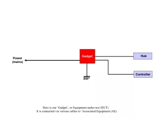
Hub Gadget Power (mains) Controller Here is our ‘Gadget’, or Equipment-under-test (EUT). It is connected via various cables to ‘Associated Equipment (AE)
Hub Gadget Power (mains) Controller In our ‘real’ world, we are subject to some RF energy from intentional and unintentional transmitters
Induced RF interference Hub Gadget Power (mains) Controller Which may be induced into our cables.
Hub Gadget Power (mains) Induced RF interference Controller Even the earthing strap
Hub Gadget Power (mains) Controller Even mobile phones
Induced RF interference Hub Gadget Power (mains) Controller Can inject signals into our cables
Equipment under test Associated equipment Hub Gadget Power (mains) Controller This defines the EUT and AE components. The EUT is the item we are testing.
Equipment under test Associated equipment Ethernet 2 core mains cable AE EUT RS232 AE Green/Yellow Earth bond wire We can describe the types of cable connected to our EUT.
Equipment under Test 150ohm environment Ethernet 2 core mains cable AE EUT RS232 AE Green/Yellow Earth bond wire In the RF world, our EUT will interact with its environment with a certain impedance. This defines how much coupling there is between the EUT and the surroundings. 150ohm is defined as a typical figure. If all testing is performed in this 150ohm environment, it provides repeatability.
Equipment under Test 150ohm environment 150ohm Impedance networks Ethernet 2 core mains cable AE EUT RS232 AE 150ohm Impedance networks Green/Yellow Earth bond wire To maintain this 150ohm environment, every connection (cable) must pass through a 150ohm impedance network.
Equipment under Test 150ohm environment 150ohm Impedance networks RF source Ethernet 2 core mains cable AE EUT RS232 AE 150ohm Impedance networks Green/Yellow Earth bond wire …..and we apply the RF stress to each cable in turn.
Equipment under Test 150ohm environment 150ohm Impedance networks Ethernet 2 core mains cable AE EUT RS232 AE 150ohm Impedance networks Green/Yellow Earth bond wire RF source …..and we apply the RF stress to each cable in turn.
Equipment under Test 150ohm environment 150ohm Impedance networks Ethernet 2 core mains cable AE EUT RS232 AE 150ohm Impedance networks Green/Yellow Earth bond wire RF source …..and we apply the RF stress to each cable in turn.
Equipment under Test 150ohm environment 150ohm Impedance networks Ethernet 2 core mains cable AE EUT RS232 AE 150ohm Impedance networks Green/Yellow Earth bond wire RF source …..and we apply the RF stress to each cable in turn.
Equipment under Test 150ohm environment 150ohm Impedance networks RF source Ethernet 2 core mains cable AE EUT RS232 AE 150ohm Impedance networks Green/Yellow Earth bond wire Note that during these tests, all cables/connections must pass through the 150ohm networks. .
Equipment under Test 150ohm environment 150ohm Impedance networks RF source Ethernet 2 core mains cable AE EUT RS232 AE 150ohm Impedance networks Green/Yellow Earth bond wire Each network is designed to suit the cable it is connected too..
RF input (50ohm source) Coupling capacitor 100R Decoupling inductor AE EUT Here is an overview of the functions of a network…..
RF input (50ohm source) Coupling capacitor 100R AE EUT It connects an RF signal onto our cable via a coupling capacitor. Note the 100ohm resistor. This is effectively in series with the 50ohm output impedance of our RF source, hence the overall impedance is 150ohm. Note that the RF is injected to the EUT and the AE
RF input (50ohm source) Coupling capacitor 100R Decoupling inductor AE EUT We are not testing the AE… so we add an inductor to ‘decouple’ the RF from the AE (this blocks the RF)
RF input (50ohm source) Coupling capacitor 100R Decoupling inductor AE EUT CDN Coupling-Decoupling Network Our network has coupling functions (coupling the RF to the EUT) and decoupling functions (blocking the RF to the AE), so we call it a CDN..
RF input (50ohm source) Coupling capacitor 200R 200R Decoupling inductor L N L N AE EUT CDN M2 type CDNs are designed to suit a particular type of cable. This is an example for a 2 core unscreened power cable
Ground Reference Plane Insulating blocks, 10cm high TEST SETUP. Conducting plate (brass, copper, aluminim, or steel) acts as our reference plane.
AE EUT AE Ground Reference Plane The EUT and AE units are positioned 10cm off the ground plane on non-conductive blocks.
AE EUT AE Ground Reference Plane The CDNs are bolted or strapped firmly to the ground plane.
AE EUT AE Ground Reference Plane And the cables connected. Note that the cables between EUT and CDNs must not exceed 30cm long.
Synth PA AE EUT AE Ground Reference Plane We may start by testing the mains power cable..
Synth 50ohm termination PA AE EUT AE Ground Reference Plane The RF input on one of the ‘passive’ CDNs is terminated with a 50ohm load. This provides the 150ohm impedance on the unused cables.
Synth. 50R terminator (fitted to 1 CDN ony) PA 6dB atten Twisted pairs T4 AE EUT Ethernet port 5 core scrnd S5 Serial port AE Power in M2 2 core mains M1 Safety ground connection Ground Reference Plane Looking at the setup in more detail…note the different CDNs used for each cable. M2 = 2 core power, T4 = 4 core telecom, S5 is a screened 5 core cable and M1 is a single core power connection. Note the 6dB attenuator in the RF feed. This is requirement of the standard.
Synth. PA Twisted pairs T4 AE EUT Ethernet port 5 core scrnd S5 Serial port AE Power in M2 M1 Safety ground connection Ground Reference Plane 2 core mains Each test must be pre-calibrated. We are using the M2 CDN for the first test. The EUT and SAE cables are disconnected……
Synth. PA Twisted pairs T4 AE EUT Ethernet port 5 core scrnd S5 Serial port AE Power in M2 M1 Safety ground connection 150/50R adaptors Ground Reference Plane 2 core mains …..and replaced by calibration adaptors.
RF feedback signal Synth. PA Twisted pairs T4 AE EUT Ethernet port 5 core scrnd S5 Serial port AE Power in M2 50ohm termination M1 Safety ground connection Ground Reference Plane 2 core mains The output from the adaptor on the EUT side is fed back to the synthesiser. This feedback allows the system controller to set the RF test level correctly across the whole scan.
Synth. PA Twisted pairs T4 AE EUT Ethernet port 5 core scrnd S5 Serial port AE Power in M2 2 core mains M1 Safety ground connection Ground Reference Plane …..and then the EUT and AE cables are reconnected, and the same settings used to apply the RF stress to the cable.
Synth. PA Twisted pairs T4 AE EUT Ethernet port 5 core scrnd S5 Serial port AE Power in M2 2 core mains M1 Safety ground connection Enhanced CDN Ground Reference Plane In order to avoid this timewasting ‘calibration’ phase, Laplace has developed the ‘Enhanced’ CDN.
Synth. Applied stress level (DC output) PA Twisted pairs T4 AE EUT Ethernet port 5 core scrnd S5 Serial port AE Power in M2 2 core mains M1 Safety ground connection Enhanced CDN Ground Reference Plane The enhanced CDN provides an additional output signal.
RF input (50ohm source) Coupling capacitor 100R Decoupling inductor AE EUT This is a standard CDN…..
Detector network Feedback output (DC) RF input (50ohm source) Coupling capacitor 100R Decoupling inductor AE EUT …..and this shows the additional network which provides a DC output signal proportional to the applied RF stress signal.
Factory Calibration Detector network Feedback output (DC) RF input (50ohm source) Coupling capacitor 100R Decoupling inductor RF stress level (V) AE EUT We calibrate this DC output level against the applied stress level.
Factory Calibration Detector network Feedback output (DC) RF input (50ohm source) Coupling capacitor 100R Decoupling inductor RF stress level (V) AE EUT ENHANCED CDN So that if we can use this DC output signal, we do not need to pre-calibrate each test.
Synth. Feedback signal PA Twisted pairs T4 AE EUT Ethernet port 5 core scrnd S5 Serial port AE Power in M2 2 core mains M1 Safety ground connection Enhanced CDN Ground Reference Plane Our synthesiser has an additional input to receive the calibrated DC signal from the enhanced CDN. This provides closed loop control of the RF stress signal level.