Download
1 / 37
370 likes | 545 Vues
CST simulations of the impedance of a new design for the PS wire scanners. F. Caspers, A. Grudiev, E. M étral, B. Salvant. Many thanks to W. Andreazza, R. Calaga and F. Roncarolo (BI). Agenda. Context Main assumptions Simulation of the wire scanner tank alone

E N D
CST simulations of the impedanceof a new design forthe PS wire scanners F. Caspers, A. Grudiev, E. Métral, B. Salvant Many thanks to W. Andreazza, R. Calaga and F. Roncarolo (BI)
Agenda • Context • Main assumptions • Simulation of the wire scanner tank alone • Simulations of the wire scanner with the wire and arm (parking position IN) • Simulations of the wire scanner with the wire and arm (parking position OUT) • Summary
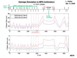
Context • 4 wire scanners are installed in the PS • Beam losses due to small aperture of current wire scanner tank design New design for wire scanner in the PS See EDMS document 999629 • Request for building the new tanks, but impedance had not been checked. • History of broken wires in the SPS due to beam induced losses "Cavity Mode Related Wire Breaking of the SPS Wire Scanners and Loss Measurements of Wire Materials" F. Caspers, B. Dehning, E. Jensen, J. Koopman, J.F. Malo, F. Roncarolo - Proc DIPAC 2003 (pdf)"Wire Measurements on the LHC wire scanner" F. Caspers, T. Kroyer, ABP/RLC meeting (pdf) 2 main risks to this new design increased impedance (longitudinal and/or transverse) can lead to instabilities increased longitudinal impedance can lead to burning the wire
What can we do to check the impedance? • Theory • Simulations • Measurements • Here we use simulations (CST) • Time domain simulates the EM interaction of a line density bunch with a 3D model CST Particle Studio Wakefield Solver • Frequency domain simulates the modes that can be excited in a 3D model CST Microwave Studio Eigenmode Solver
Main assumptions • Geometrical model • Hexahedral mesh approximates the structure • Model can be different from drawing • Drawing can be different from what is really installed!!!! • Material properties • In time domain, very coarse fit of the input frequency dependence (see work of Carlo and Lukas Haenichen of TU Darmstadt) • EM properties of materials at high frequencies are not always measured and can be very different from the model used in CST (very often, they are not part of the specs!!! Also, effect of mechanical and RF damage over time, anisotropies, inhomogeneities, etc.) See work of Tatiana, Carlo and phase 2 collimation for instance • Specific issues of modeling a thin wire (see work of Tom Kroyer CERN-AB-Note-2008-018 ) • Interaction with the bunch (Particle Studio) single pass of a line current density (see work of Carlo and Prof. Vaccaro) limited wakelength limitated to low Q values in MWS, perturbation method, well suited to high Q values and no thick dispersive materials
Agenda • Context • Main assumptions • Simulation of the wire scanner tank alone • Simulations of the wire scanner with the wire and arm (parking position IN) • Simulations of the wire scanner with the wire and arm (parking position OUT) • Summary
1. Wire scanner tank alone CST model after import and processing STP model exported from CATIA Reasons for changing the tank: - improve aperture - enhance measurement accuracy
Note: import a model from CATIA • Method currently used: • Ask the model owner to export it in *.STP format • Open the *.STP file in HFSS (and check the structure…) • Export in *.SAT format • Import the *.SAT in CST • Suppress unnecessary parts and use the CST healing functions • Fill the simulation space with vacuum and use the separate shape function on the resulting solid to keep the vacuum inside the element and suppress the vacuum around it. • Current issues: • CERN does not have a direct import license for CATIA or STEP files, hence the need to go through HFSS • CATIA models are only accessible through SMARTEAM, a shared environment (2-week-training course required) • Resulting models in CST sometimes present serious issues, and obtaining a consistent model is not always trivial
Longitudinal wake from CST Particle Studiobeta =1, sigma = 2 cm, 2 M mesh cells, wake of ~20 m, indirect testbeams wake integration 1.45 GHz 1.18 GHz 0.95 GHz 1.12 GHz 0.9 GHz 0.8 GHz
Eigenmodes of the tank Very small !!! Remarks: Q is obtained with the formula with W= total stored energy and P=dissipated power (W=1J in eigenmode) (linac convention) Perturbation method id used to obtain the Q and R for stainless steel.
Power losses calculations • If we assume the mode frequency overlaps with one of the beam harmonics (conservative approach) • With the parameters of the LHC nominal beam at ejection of the PS • nominal bunch charge after splitting q = 18.4 nC (1.15 e11 p/b) • bunch spacing = 25 ns (worst case scenario) • smallest nominal RMS bunch length = 30 cm • Rs is the shunt impedance (linac convention) • z is the rms bunch length in m
Why is the dissipated power so small? Bunch power spectrum for LHC type bunches of various lengths = 30 cm (PS ejection nominal) = 20 cm (PS ejection smaller emittance) = 11 cm (LHC injection) = 7.5 cm (LHC ejection) Peaks higher than 0.5 GHz are washed out by the large bunch length in the PS With LHC bunches with small longitudinal emittance, bunch length is around 20 cm, and dissipated power for mode 1 becomes 0.3 W.
Agenda • Context • Main assumptions • Simulation of the wire scanner tank alone • Simulations of the wire scanner with the wire and arm (parking position IN) • Simulations of the wire scanner with the wire and arm (parking position OUT) • Summary
2. Wire scanner tank with wire and mechanical system CST model after import and processing STP model exported from CATIA Wire at parking position (OUT) CST model after import and simplification fork Mechanical system Wire after scan (IN) Ion pump
Tank with wire (IN position)Longitudinal impedance beta =1, sigma = 3 cm, 2 M mesh cells, wake of ~20 m Fork and casing in stainless steel, wire as PEC wire Additional simulation with Eigenmode solver (152,000 mesh cells) f0 =292 MHz Rs= 43 k Q= 1200 total power loss in the structure P=800 W for this mode
Is this new mode an issue? Fork and casing in stainless steel Compare with the losses of the old design Additional simulation with Eigenmode solver (156,000 mesh cells) f0 = 292 MHz Rs= 8.7 k Q= 730 total power loss in the structure P=160 W for that mode (new design 800 W)
Surface currents (freq domain) Old design New design
Voltage in the wire (1st try…) Old design New design Charge of the bunch = 1 nC Rms bunch length: 20 cm R=1.43 Ohm P = V2/R = (0.004*18.4)2/1.43 = 4 mW peak in the wire this method should be crosschecked with the SPS case for which wires actually broke
Trying to damp this 300 MHz mode • Putting some dispersive materials in the structure helps reducing losses due to HOM: Fritz: 1) Losses are proportional to Rs “ P = Rs I2 ” 2) Rs/Q is constant whatever the material 3) Both Rs and Q decrease if we create losses in dispersive materials 4) “ P = Rs/Q *Q I2 ” create EM losses with dispersive materials lower Q for that mode fewer losses! However, of course more losses at low frequencies are expected, and we should be careful with the transverse impedance
First try to damp that modes with available blocks of ferrite • William says the only possible spots for ferrites are on the top and bottom • They already have 4S60 ferrite plates and they would like to use them if possible. Possible positions
Where do we put the ferrite plate Proposed position for the ferrite
Longitudinal impedance (real) Rms bunch length 20 cm All materials ss304L except wire Ferrite 4S60 Time domain wakefield solver Nice damping! frequency shifts down
Longitudinal impedance (imaginary) Not too much additional low frequency longitudinal impedance maybe not expected to be checked Im(Z/n) = 0.07 to 0.08
Horizontal “dipolar” impedance (LF) No symmetry… We displace the beam by 10 mm towards the engine and look for the slope of the horizontal impedance (first approximation) Imaginary LF horizontal “dipolar” impedance =(20-8)/0.01= 1.2 k/m
Vertical dipolar impedance (LF) There is a symmetry in the vertical plane Imaginary LF vertical dipolar impedance =13/0.01= 1.3 k/m
Agenda • Context • Main assumptions • Simulation of the wire scanner tank alone • Simulations of the wire scanner with the wire and arm (parking position IN) • Simulations of the wire scanner with the wire and arm (parking position OUT) • Summary
Tank with wire (OUT position) No other harmful mode detected Longitudinal: Z/n=0.04 Ohm horizontal: 0.9 kOhm/m Vertical: 0.5 kOhm/m Mode due to the wire and fork
Summary • Need to check the new wire scanner design for the PS • From these simulations, new design seems to create more longitudinal impedance and more losses. • From the figures obtained, this increase does not appear huge • What should we do? recommendation for short term: build like this and be ready to install ferrites if needed. recommendation for longer term: Compare these figures with simulation of the SPS wire that broke. Perform wire measurements when the tank is built. optimise the position, shape and material of the ferrites
Mode 3 H field E field
Horizontal dipolar impedance at low frequency LF simulation parameters: 40,000 mesh cells Rms bunch length=20cm