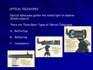
IP and Optical: Better Together?
LTS. IP and Optical: Better Together?. Ann Von Lehmen Telcordia Technologies 732-758-3219 AVL2@research.telcordia.com. IP and optical networks: how to build a network that handles IP traffic but that optimizes overall network performance and cost. Outline. Optical Networks 101


IP and Optical: Better Together?
E N D
Presentation Transcript
LTS IP and Optical: Better Together? Ann Von Lehmen Telcordia Technologies 732-758-3219 AVL2@research.telcordia.com
IP and optical networks: how to build a network that handles IP traffic but that optimizes overall network performance and cost
Outline • Optical Networks 101 • What can optics do for the IP layer? • Transport • Restoration • Reduce the cost of routing IP traffic • Traffic engineering • Paradigms for closer interworking • how far to go?
Router Router ONE ONE ONE Router Basic Network: IP routers + Optical network elements End Customer Router Router Optical Network
Optical Networks 101: Wavelength Division Multiplexing (WDM) Single Fiber Single Amplifier Multiple Fibers Multiple Amplifiers WDM = A Capacity Multiplier Technology development has been driven by the need for bandwidth Source of the traffic growth is the Internet The Internet is still estimated to be growing at 100%/year Networks need to grow in capacity by 32x in 5 years! .
Optical Network Building Blocks: Point-to-Point Wavelength Multiplexing Systems • Multiplexing of as many as ~200 wavelengths on a fiber (“Dense WDM”, or DWDM) • Rates of 2.5 and 10 Gb/s; work on 40 Gb/s systems underway • Significant deployment in long haul networks (largest aggregation of traffic, long distances) • Products available from many manufacturers (Ciena, Nortel, Lucent,...) • Optical layer fundamentally provides transport of IP packets
OXC Input fibers with WDM channels Output fibers with WDM channels Optical Network Building Blocks: Optical Cross-Connects (OXCs) • OXC switches signals on input {wavelengthi, fiberk} to output {wavelengthm, fibern}
OXC Input fibers with WDM channels Output fibers with WDM channels Optical Cross-Connects (OXCs) • ‘Opaque’: o-e, e-o, electronic switch fabric • ‘Transparent’: o-o-o, optical switch fabric • Hybrid, (o-e-o): optical switch fabric, o-e-o • Hybrid: both opaque and transparent fabrics • Tunable lasers + passive waveguide grating
Lucent MicroStar MEMS Based Mirror Array Technology Source: [Butt] 44 array of 2-axis micromirrors Optical X-C 2-axis Micromirror Inside the Cross Connect: All Optical Switch Technologies: MEMS Schematic Drawings of a Micro-machined Free-Space Matrix Switch Source: Scanned from [9.Lin] Detail of the Switch Mirrors
IP Router IP Router IP Router IP Router Important optical layer capability: reconfigurability IP Router OXC - A OXC - C OXC - B OXC - D Crossconnects are reconfigurable: • Can provide restoration capability • Provide connectivity between any two routers
Architecture 1: Big Fat Routers and Big Fat Pipes Access lines A Z Access lines • All traffic flows through routers • Optics just transports the data from one point to another • IP layer can handle restoration • Network is ‘simple’ • But….. • - more hops translates into more packet delays • - each router has to deal with thru traffic as well as terminating traffic
Architecture 2: Smaller routers combined with optical crossconnects OXC OXC OXC OXC • Router interconnectivity through OXC’s • Only terminating traffic goes through routers • Thru traffic carried on optical ‘bypass’ • Restoration can be done at the optical layer • Network can handle other types of traffic as well • But: network has more NE’s, and is more complicated
Performance/cost comparisons: Networks with and without OXC’s • Performance Considerations • IP Packet delays--# of hops • Restoration • traffic engineering--efficient use of network resources • Handling multiple types of services • Cost Considerations • Number of network elements (equipment and operations costs) • Different types of ports (IP and OXC) and total port costs • Fiber costs and efficiency of fiber and usage • Static vs dynamic cost analysis
Paccess ••• ••• Cost Analysis:Compare the two architectures CR = router port cost per COXC = OXC port cost per = factor representing statistical multiplexing = Pthru/Pterm Paccess Pterm Pthru Pthru ••• ••• OXC Pthru Pthru Pterm Total Backbone Port Cost (1+2)PtermCR Total Backbone Port Cost 2(+1)PtermCOXC + PtermCR Router only cost is less when CR = CR/COXC < (+1)/
Use OXCs CR = CR/COXC 2 Use BFR Statistical Muxing Factor 3 4 5 Use OXCs 10 Use BFR = Pthru/Pterm Results: BFR = Big Fat Router OXC=Optical Cross Connect
IP / WDM Traffic Engineering • Traffic Engineering Objectives • The goal of traffic engineering is to optimize the utilization of network resources • reducing congestion & improving network throughput • more cost-effective • efficiency gained through load balancing • requires macroscopic, network wide view • IP Layer TE Mechanisms • MPLS Explicit Routing • WDM Layer TE Mechanisms • WDM Lightpath Reconfiguration - IP Network Topology Reconfiguration
IP layer traffic engineering • In conventional IP routing, each router makes an independent hop-by-hop forwarding decision • routes packets based on longest destination prefix match • maps to next hop • In MPLS, assignment of a packet to a FEC is done just once as it enters the network, and encoded as a label, each label is associated with a path through the network • label sent along with the packet for subsequent routers to find the next hop • MPLS: explicit control of packet paths: • simpler forwarding • easy support of explicit routing: label path represents the route • MPLS uses a set of protocols for signaling and routing BUT, IP layer traffic engineering is constrained by the underlying network topology
Traffic Engineering Using Network Topology Reconfiguration Simulation Studies -- AT&T IP Backbone
Effect of reconfiguration on link load distribution CA CA NY CH NY CH DV SF DC DV SF DC SL SL LA LA AT reconfigured original AT DL DL 100 OL OL 80 60 90%+ 70 ~ 89% 40 ~ 69% 39%- utilization (%) 40 20 0 1 3 5 7 9 11 13 15 17 19 21 23 25 27 29 31 33 35 37 link ID
PM Traffic Demands and Link Load Distribution CA CA NY NY CH CH DV DV SF SF DC DC SL SL 90%+ 70 ~ 89% 40 ~ 69% 39%- LA LA AT AT original reconfigured DL DL 100 OL OL 80 60 utilization (%) 40 20 0 1 3 5 7 9 11 13 15 17 19 21 23 25 27 29 31 33 35 37 link ID
Network Reconfiguration for Traffic Engineering Tremendous value…….. • Congestion relief, load balancing • Cost savings in router ports • 44% in this simulation • WDM layer reconfiguration works in concert with IP layer TE (i.e., MPLS)
IP and the optical layer: Recap: Reconfigurable optical layer offers: • ultra-high capacity transport • lower cost node architecture • enhanced traffic engineering capability • Next: • IP/WDM network management paradigms • IP and optical layers are independent • The optical overlay model • IP and optical layers are integrated • for rapid provisioning and most efficient use of network resources?
Service Management Element Management System Network Element Network Element Network Element Network Management End Customer Other Operations Support Systems Network Management System Network Database NE’s = Optical, IP, SONET, etc
Dynamic Networking • In a static world: Infrequent need to traffic engineering put connections up and leave them ‘for 20 years’ centralized net management works beautifully • Coming soon? • Need to accommodate service requests on a more dynamic basis • Centralized network management may not be able to respond rapidly enough, and is not scalable • Service drivers for dynamic networking • Variable bandwidth on demand • Storage Area Networks (SAN) • Disaster recovery networks • High-speed Internet connectivity to ISPs and ASPs.
Optical Network Optical Network New paradigm: • Bandwidth requests from IP layer are serviced directly by the optical layer • Routing within the optical network uses IP-MPLS protocols: Autodiscovery of neighbors(routing table), path selection according to service parameters(bit rate, level of protection, etc), signaling to establish path through the network • ‘Intelligent’ domain, interfaces Customer NNI UNI UNI Network Database IP/MPLS routing protocols
IP Router IP Router IP Router IP Router 1. Router requests a new optical connection 3. Path set-up message propagates through network 4. Connection is established and routers are notified Example: Dynamic Set-Up of Optical Connection OXC - A OXC - C OXC - B 2. OXC A makes admission and routing decisions
Traditional R R EMS NMS R R OXC OXC OXC OXC OXC OXC OXC OXC OXC OXC Distributed management and ‘intelligent’ optical networks R I. R Optical Network R R NMS’, EMS’ ‘Self-Managing’ II. • On-Demand Optical Path • Automated Provisioning • Auto-Discovery • etc Intelligent Optical Network UNI
Required Functionality in UNI 1.0 • Rapid provisioning of circuits between clients • Various levels of circuit protection and restoration • Signaling for connection establishment • Automatic topology discovery • Automatic service discovery • Optical Internetworking Forum is pursuing UNI and NNI definitionUNI 1.0 defined; UNI 2.0 under development NNI under development (ETA 12/02) • All major vendors have implemented ‘control plane’; carrier deployment just beginning
Recap: (client/server paradigm) • Client network routing protocol and optical network routing protocol are run independently (they may use the same protocols). • There is no exchange of routing information between client and optical layers. • So coordination eg for traffic engineering, or for restoration, is still moderated by a centralized management system.
Further integration of IP and optical planes: Peer model • Peer Model • A single routing protocol instance runs over both the IP and Optical domains • A common protocol is used to distribute topology information • The IP and optical domains use a common addressing scheme.
Peer Model • No ‘UNI’: The entire client-optical network is treated as single network. The same protocols (G-MPLS) are used in both optical and client equipment. • Client devices (e.g. routers) have complete visibility into the optical network, and are responsible for computing paths and initiating connections • I.e., Routers[clients] have the intelligence, and hold network info Router[Client] Network Router[Client] Network Optical Network
Optical subnet Optical subnet Optical Subnet The ultimate vision: integrated IP/optical management GMPLS for signaling and routing within the Optical Network Router Network Optical Transport Network NNI NNI OTN GMPLS Sig. End-to-end GMPLS Sig. Connection provisioning independent of the management layer.
Summary • Optical networking is core to the development of IP networks and services • Both transport and switching • How far things will go towards ‘the ultimate vision’ is an open question • More than IP traffic in networks (GbE, SONET) • Dynamic service provisioning: when? • Policy, security and interoperability issues • Large carriers have a lot of inertia • Transitions to new paradigms cost money