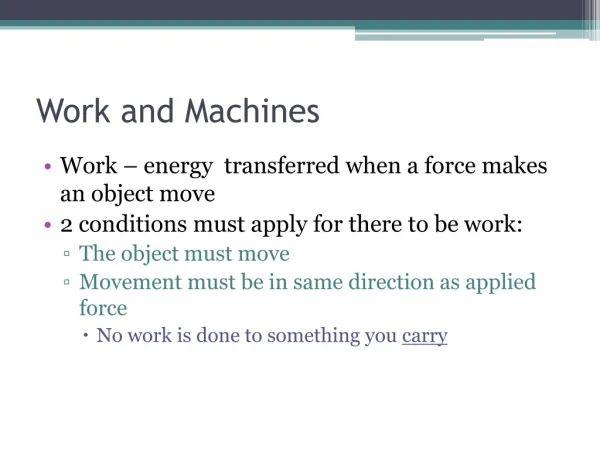
Work and Machines
Work and Machines. Simple Machines. The six types of simple machines are: the lever the wheel and axle the inclined plane the wedge the screw the pulley. Levers. a rigid bar that is free to move around a fixed point . The fixed point the bar rotates around is the fulcrum .

Work and Machines
E N D
Presentation Transcript
Simple Machines • The six types of simple machines are: • the lever • the wheel and axle • the inclined plane • the wedge • the screw • the pulley
Levers • a rigid bar that is free to move around a fixed point. • The fixed point the bar rotates around is the fulcrum. • Levers are classified into three categories based on the locations of the input force, the output force, and the fulcrum. • To calculate the ideal mechanical advantage of any lever, divide the input arm by the output arm.
First-Class Levers • In a first-class lever, the fulcrum is always located between the input force and the output force. • Example See-saw, scissors, & tongs
Second-Class Levers • In a second-class lever the output force is located between the input force and the fulcrum. • Example bottle opener
Third-Class Lever • In a third-class lever the input force is located between the fulcrum and the output force. • Example baseball bats, hockey sticks, & golf clubs
Wheel & Axle • a simple machine that consists of two disks or cylinders, each one with a different radius. • The outer cylinder is the wheel and the inner cylinder is the axle • the steering wheel the driver turns is the wheel, and the shaft that rotates with it is the axle.
Wheel & Axle • To calculate the ideal mechanical advantage of the wheel and axle, divide the radius (or diameter) where the input force is exerted by the radius (or diameter) where the output force is exerted.
Inclined Planes • a slanted surface along which a force moves an object to a different elevation. • Wheelchair ramp is an example of this • The ideal mechanical advantage of an inclined plane is the distance along the inclined plane divided by its change in height.
Wedge • AV-shaped object whose sides are two inclined planes sloped toward each other. • A thin wedge of a given length has a greater ideal mechanical advantage than a thick wedge of the same length. • Examples are a knife blade, which cuts best when its edge is sharp, and a zipper, which uses a wedge to separate and join the zipper's teeth.
Screw • An inclined plane wrapped around a cylinder. • Screws with threads that are closer together have a greater ideal mechanical advantage.
Pulleys • Asimple machine that consists of a rope that fits into a groove in a wheel. • Ideal mechanical advantage of a pulley or pulley system is equal to the number of rope sections supporting the load being lifted.
Fixed Pulleys • Wheel attached in a fixed location. • Examples of fixed pulleys include the pulley at the top of a flagpole and the pulleys used to pull up blinds.
Movable Pulleys • is attached to the object being moved rather than to a fixed location. • Sailors use movable pulleys to pull in sails, and skyscraper window washers stand on platforms suspended by movable pulleys.
Pulley System • Combines fixed and movable pulleys. • Cranes
What system requires the smallest input force to lift a 2500-N load?
Determine the actual mechanical advantage for each of the systems for a 2000-N input force.
Which of the three systems shown in the graph consists of a single fixed pulley? Explain how you know.
Describe what happens to system B's output force as the input force increases above 4000 N. How does this affect the mechanical advantage of the system at higher loads? Offer a possible cause for the performance shown in the graph.
Using the mechanical advantage value from Question 2, determine the output force of system A for an input force of 8000 N.
Compound Machines • a combination of two or more simple machines that operate together. • Many familiar compound machines, such as a car, a washing machine, or a clock, are combinations of hundreds or thousands of simple machines.