Download
1 / 66
660 likes | 798 Vues
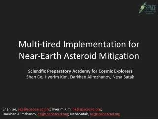
This research outlines a comprehensive three-tiered framework for exploring and mitigating the risks posed by Near-Earth Asteroids (NEAs) with a reference mission focused on asteroid 99942 Apophis. Our strategy combines precision tracking, detailed scientific investigations into the asteroid's properties, and multiple mitigation techniques to neutralize potential threats effectively. Key milestones, from initial exploration to permanent mitigation, are highlighted, ensuring a robust approach to planetary defense. The initiative leverages advanced technologies and experimental platforms to secure the safety of Earth from asteroid impacts.

E N D
Multi-tired Implementation for Near-Earth Asteroid Mitigation Scientific Preparatory Academy for Cosmic ExplorersShen Ge, Hyerim Kim, Darkhan Alimzhanov, Neha Satak Shen Ge, sge@spaceacad.org; Hyerim Kim, hk@spacecad.org; Darkhan Alimzhanov, da@spaceacad.org; Neha Satak, ns@spaceacad.org
NEO Mitigation Strategy • Detailed three-tiered layer for exploring and mitigating Near Earth Asteroids (NEAs) • Reference mission to asteroid 99942 Apophis is the proof of concept for this process Apophis Exploration and Mitigation Platform LEO Flight Experiments Ground Experiments and Simulations
Apophis Exploration and Mitigation Platform (AEMP) 2023 NOV • Exploration and mitigation platform to Apophis. Scheduled Objectives: • 1. Begin a mission with precision tracking, “tagging” the asteroid with the spacecraft, and combine this with science measurements of the gravity field, material composition, and thermal properties. [2021] • 2. Cross-correlate the tracking data found in the initial exploration phase with SDM predictions and resolve the modeling and parameter uncertainties. [2021 – 2022] • 4. Perform an initial mitigation technique that depends on the least data (mass distribution, total mass, center-of-mass location, geometric envelope, spin state). [2022] • 5. Combine the initial mitigation phase with continued observation to map the albedo, model the thermal properties, model solar pressure, and the Yarkovsky effect. [2022-2023] • 6. Finally, apply some permanent mitigation technique that can eventually retire the threat completely. [2023] 2021 FEB
AEMP: Mission Profile • Intermediate Analysis • Short Term Mitigation – Apr 2022 • Long Term Mitigation – May 2023 • Preliminary Analysis • Preliminary Exploration • Rendezvous – Sep 2021 • Cruise • Launch – Feb 2021 • Post Mitigation Investigation • End of Mission – Nov 2023
AEMP: Orbital Transfer 2021 SEP • Simple 2-impulse orbit transfer • Direct launch-to-transfer orbit using a Falcon-9 vehicle • Solid kick motor provides majority of rendezvous ΔV • Upon insertion into the proximate heliocentric orbit near Apophis, the spacecraft is to take up a 2 to 3 km stand-off position to begin exploration • Proximity maneuvers performed by mono-propellant Hydrazine main engine and attitude control thrusters 2021 FEB
Why is Exploration Needed Before Mitigation?(J. D. Giorgini, L. A. M. Benner, S. J. Ostro, M. C. Nolan, and M. W. Busch. “Predicting the Earth encounters of (99942) Apophis”, Icarus 193 (2008) 1-19.) • Errors in the Standard Dynamical Model (SDM) can produce tens of Earth radii positional errors over the period 2029 - 2036 • Uncertainties in Apophis’ thermal emission parameters (e.g. bond albedo) can produce tens of Earth radii errors over the period 2018-2036
AEMP: Initial Exploration Phase 2022 APR 2021 SEP The first actions to be performed are designed to achieve the following science objectives: • Determine the trajectory of Apophis 99942 with sufficient accuracy to establish the minimum trajectory change that can guarantee no Earth impact through the close approach of 2036 • Study physical characteristics • to refine the orbit propagation models. • Spin state • Asteroid mass, etc. • to refine intervention procedures. • Surface mapping of geometric albedo • Gravity model valid ~100m from surface
AEMP: Instrumentation/Science Mapping 2022 APR 2021 SEP • Optical Navigation Camera • Laser Range Finder • Radio Science • Inertial Measurement Unit • Star Tracker • Micro-bolometer
Suppose we launch early (2012), and acquire tracking data over the following year. Then as we propagate forward over a long time period using the dynamical model, the uncertainty (tube width) might grow so large that an unambiguous prediction is impossible by 2036. Make tracking measurements and incorporate data into trajectory model Nominal trajectory Tracking and Mitigation Pose Conflicting Requirements Whereas, if we launch and do tracking just before a close approach, our uncertainty will be smaller but there will be no time for mitigation. Tracking measurements 9
AEMP: Tracking Error vs. Deflection Effectiveness Tracking begins 1/10 Earth Radius 3 Earth Radii April, 2029 close approach
AEMP: Gravity Tractor 2023 MAY 2022 APR • The gravity tractor is well-known and can be applied early in mission since detailed knowledge of the physical properties of the NEO is not required. • The thrusters used are xenon Hall Effect thrusters canted Φ = 38˚off the thrust axis and providing a net tractor force of Fhover = 4 mN. • By maintaining a position d = 270m from C.O.M. of Apophis for 1 year (prior to the 2029 close approach), 3 Earth radii of deflection will be achieved by 2036.
Yarkovsky Effect Cooler “dawn” side Net force Solar Radiation hotter “dusk” side Excess radiation Carries away momentum Pphotonper photon D. Vokrouhlicky, A. Milani, and S. R. Chesley. “Yarkovsky Effect on Small Near-Earth Asteroids: Mathematical Formulation and Examples”, Icarus 148, 118-138 (2000).
AEMP: Surface Albedo Treatment System (SATS) 2023 NOV 2023 MAY • SATS raises or lowers the average albedo to produce a three-Earth-radii orbit deflection by 2036. • On the sun-facing side, the surface has a net positive charge. • The SATS nozzle is designed to impart a negative charge to the ACPs and dispensing is performed solely on the sun lit side. • This effect further ensures that the particles will be quickly bound to the surface and will not rebound or levitate into an escape condition. P. Lee, “Dust Levitation on Asteroids”, Icarus 124, 181-194 (1996)
AEMP: Surface Albedo Treatment System (SATS) 2023 NOV 2023 MAY A secondary flow is released into the outer portion of the selected ACP chamber The ACP storage chamber is double-walled; the ACPs being contained within the inner wall. The inner wall is perforated by many small holes. The gas flows through the holes in the inner wall, both “fluidizing” the ACP mass (mixing up the ACPs so that the dry powder behaves like a liquid) and expelling a steady stream of ACPs into the mixing chamber. Fluidization stream ACP Chamber Albedo Change Particles Pressurized Inert Gas Tribo ionization tube Mixing Chamber The main flow out of the gas supply leads directly to the mixing chamber. Once mixed, the ACPs plus gas is forced through the narrow tribo ionization tube
AEMP: ACP Mass Calculation 2023 NOV 2023 MAY
AEMP: Spacecraft Design • Mass: • Launch mass to Earth escape = 1100 kg • Wet mass = 570 kg • Dry mass = 415 kg • Power: • Solar arrays • Li-Ion battery packs • Max power mode = Grav Tractor ~ 1kW • Attitude control system provides 3-axis stabilization • Reaction wheels • Attitude thrusters provide minor translational capability • Propulsion • Solid kick motor for rendezvous ΔV • Hydrazine monopropellant system for proximity operations • 2 Xenon propellant Hall’s effect thrusters • Semi-autonomous command structure • Communications • 1 m parabolic high gain antenna • 2 omni directional low gain antenna Development time: ~5yrs Total cost: ~ $350 M • Sensor suite • Star tracker • Inertial measurement unit • Optical navigation cameras • Sun sensors • Laser range finder • Micro-bolometer
AEMP: Cost Justification • Costing exercise was done at Ames Mission Design Center in April 2009 • Spacecraft and payload cost estimated using parametric cost estimation models • Other costs modeled as percentage warp-factors • Phase E/F costs based on historic Discovery class missions
LEO Flight Experiments (LFE) • The Apophis Mitigation Technology LEO Flight Experiments (LFE) will demonstrate feasibility of an albedo changing prototype on a target surface in a controlled environment • Static Preliminary Albedo Demonstration Experiment (SPADE) design is a cube-shaped spacecraft 40x40x40 cm • Static, flat SATS test surface is part of satellite and exposed to LEO environment 2013 FEB 2012 DEC
LFE: SPADE Design Pressurant Gas Canister Powder Canister Torque Rod (3) Sun Sensor (4) Tribodispenser Tube Electronics Bay Batteries Antenna Camera Test Surface
LFE: Mission Profile V∞ 1. Orient spacecraft 2. Charge test surface then remove power supply 3. Initiate tribodispenserand spray test surface
LFE: Mission Profile (Part 2) 4. Allow particles time to cure 5. Observe, record, and transmit data Data
LFE: Orbital and Attitude Requirements • Orient so that panel is facing sun when on sun side of earth to allow particles to cure in sunlight • Orient so main body of the craft shields the panel while moving through LEO atmosphere • Main body in ‘ram’ direction, panel in ‘plasma wake’ * To avoid excess radiation, altitude < 700 km but for 30-day mission timeline, altitude > 300 km ** Communications with College Station, TX ground station requires > 31o
LFE: Surface Design • Surface simulated by charged aluminum plates of varying roughness • Surface charge from parallel plate capacitor • Required electric field based on expected asteroid charge density E
LFE: Mass Budget EELV Secondary Payload Adapter GUMSTIX Computer Camera (Cosmos-1 adapted) Magnetometer Sunsensors (x4) Magnetorquer (x3)
Ground Experiments (GE) • Ground tests to determine optimal parameters for design of tribodispenserthrough repeated experiments with combinations of varying inputs. • Outputs to be maximized: • Charge-mass ratio (Q/M). This is immediately out of tube. will not be the same for each particle but we want the charge to be +/- 10-6 Coulombs (C) within 1 standard dev (σ). • Albedo Change (AC). Difference between albedo after treatment with albedo before treatment. This will mostly depend on the pigmentation of the powder. • Coverage area-mass ratio (A/M). • First pass transfer efficiency (FPTE). Mass of powder on surface over total mass after one trial. 2012 2010
GE: Experimental Parameters • ASSUMED CONSTANTS: • Powder (developed by PCRG for our application) • Surface temperature (400K) • Surface roughness (distributed according to asteroid) • Surface material (LL Chondrite mod) • Surface charge (5 V) Secondary variables affecting the experiment are not shown! Comment: This chart only shows direct correlation. Obviously there’s indirect correlations as well. For instance, particles that have greater charge/mass ratio (Q/M) are more likely to “stick” to the surface and hence produce a larger albedo (AC).
GE: Objective Hierarchy AHM: Weights: Albedo change is the most important objective criteria. Coverage area-mass ratio is the least important.
GE: Optimization of Design • Conduct multiple runs of experiments with varying input parameters. • Obtain average and standard deviation of runs. • Give a measure of “goodness” to each output result (Q/M, AC, A/M, and FPTE) of each set of input parameters. • Multiply each “goodness” by the weights defined in objective hierarchy and sum them to obtain one number for each setup. The setup with the maximum number is the one to use.
GE: Minimizing Experiment Runs • A full factorial experiment assuming two levels of factors, 2n runs are necessary where n is the number of independent parameters. • Using Taguchi methodology, this can be cut to 2(n+1) runs depending on number of considered interactions. • Orthogonal array/Taguchi Method assumes interactions between variables are negligible unless otherwise stated.
GE: Experimental Schematic Lamp Faraday cage SATS Infrared heater Triboiontube of SATS Nozzle Aluminum plate Faraday cages Vacuum Chamber Electrometer Electrometers Gas Tank • Not shown: • - DAQ + Computers • Scale (to measure mass of SATS before and after each run as well as mass of plate before and after each run) • Cameras (to take photos of plate before and after each run for albedo and coverage area analysis AND flow) • Thermistors (measure temperature of plate)
Simulation Outline • Particle deposition simulator simulates particle dynamics from spacecraft to surface • Inputs are design parameters such as tribodispenser length, particle size, spacecraft hovering height, etc • Outputs are particle trajectories, charge-mass ratio, albedo change, etc • Works concurrently with ground experiments to optimize design
Simulation Outline • Nine sections, split into two groups • Sections 1-4 focus on gas-particle flow where pressurized gas forces dominate • Sections 5-9 focus on interspatial and asteroid based forces where these forces dominate
Sim: Near Field Input Parameters Output Parameters Materials - Average particle size and density, particle volume fraction, particle velocity Configuration - Length and Diameter of the tube Pressurant application - Injection pressure, dilution pressure, vortex pressure • Mass flow rate • ACP charge • Gas Pressure • Particle Positions, Velocities, Accelerations • -> Distribution
Sim: Near Field 1. a) ACP/Gas Flow • - Governing Equations: • 1) Mass conservation eqn. • 2) Momentum Conservation eqn. • Turbulent air flow • - The standard κ-ε model
Sim: Near Field - Rate of particle collisions with tube walls For Charge per mass: 1. b) Electrostatic Charging
Sim: Near Field -> predicts the trajectories of the particles -> stepwise integration over discrete time steps -> solved in each coordinate direction to predict the velocity and position of the particle at given time. - Lagrangian Approach the equation of motion for the particles 2. a) Solid particle motion 2. b) Electrostatic Field • Consider the space charge from nozzle to near field, and • interactions between particle - particle. • Laplace equation
Sim: Near Field First Tribo dispenser Model (Solidworks)
Sim: Near Field Tribo dispenser Model (Gambit) Volume Meshes Set Boundary conditions
Sim: Far Field I Spacecraft Height Position Inputs Asteroid Size and Shape Forces (acceleration) From outputs of near-field Asteroid Mass Density ACP Position Asteroid Surface Charge Density ACP Velocity ACP Position Outputs ACP Acceleration ACP Velocity ACP Density ACP Charge ACP Acceleration ACP Radius Numerical integration of force equations propagated ACP Charge Note: All variable constants are outlined in red.
Sim: Far Field I Gravitational Force (Fg) G – gravitational constant M – mass of Apophis m – mass of ACP r – distance between mass centers of Apophis and ACP Electrostatic Force (FE) q – charge of ACP σ – surface charge density of Apophis A – incremental surface area Solar Radiation Force (Fr) S – solar flux A – surface area of Apophis c – speed of light v – velocity of ACP Qpr – radiation pressure coefficient
Sim: Far Field I • Starting at t=0, n powders are ejected from spacecraft at an altitude h with some velocity and acceleration. Eject more n powders every tint seconds. • Velocity and position is propagated forward in time using Newton-Euler equations and Runge-Kutta integration with time step Δt. • Detect when powders are ~1 meter above the surface and pass the simulation of Far-Field 1 to Far-Field 2.
Sim: Far Field II Position Inputs Plasma Sheath Thickness Forces (acceleration) From outputs of Far-Field 1 Solar Wind Mach Number ACP Position Plasma Sheath Potential ACP Velocity ACP Position Outputs ACP Acceleration ACP Velocity ACP Density ACP Charge ACP Acceleration ACP Radius Numerical integration of force equations propagated ACP Charge
Sim: Far Field II • A plasma sheath of negatively charged particles floats right above the surface and screens out the positive charges on the surface. • The powder particles must be able to “punch” through this cloud. • Once the ACP enters the sheath, its ultimate fate can only be one of three possibilities: • It falls to the surface. GOOD • It gets deflected and totally escapes. NOT GOOD • It becomes suspended in the sheath. NOT GOOD Powder Paths Layer of charged electrons Asteroid
Sim: Far Field II • Solve two pairs of equations: Force Current
Sim: Far Field II • Take position, velocity, and acceleration of particles from FF1. • Propagate positions and velocities of particles through FF2 forces. • Relay outputs to FF3 as inputs after undergoing a certain plasma sheath thickness.
Sim: Far Field III • After passing through the sheath, the particles will hit the ground. • But will the ground be • Shadowed (negatively charged) or sunlit (positively charged)? (Will the particle be repelled or attracted at certain places?) • Hilly or flat? (Will the particle bounce upon impact? How will this affect coverage area?) • Rocky or soft? (Will the particle bounce upon impact?) • Light or dark? (Will the particle create much albedo change?)
Sim: Far Field III • Current simulation efforts take into account a distribution of albedo and heights on surface generated by: • Create a realistic needle map n(i, j) of the surface where (i, j) is a particular pixel in the MxN image matrix. A needle map is just a matrix of normal vectors to the surface. • Assume a solar position relative to the surface. This determines the direction of the lighting. • Create an intensity map of an asteroid dependent on the needle map. • Find the geometric albedo at every pixel by assuming a Lambertian model. • Apply ACP positions from outputs of FF2 for both colors. Find the amount of albedo change detected for either case. • Currently just using a rough probability of landed particles for generating the normal distribution of ACP landings for particles.
Sim: Far Field III • Assuming 500 m2 coverage, i.e. 1.4% area coverage for the smallest possible size
Conclusion • Three-tiered design process of AEMP mission, LEO test flight satellite mission, and ground experiments with simulations is progressing concurrently providing insight on all three layers of design • Continued collaboration between the three design layers will culminate in the launch of a fully functioning spacecraft to the near earth asteroid Apophis early 2022