Download
1 / 99
990 likes | 1.13k Vues
Design of a Surface Albedo Modification Payload for Near Earth Asteroid (NEA) Mitigation. Scientific Preparatory Academy for Cosmic Explorers Shen Ge, Hyerim Kim, Darkhan Alimzhanov, Neha Satak. Shen Ge, sge@spaceacad.org ; Hyerim Kim, hk@spacecad.org ;

E N D
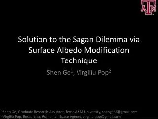
Design of a Surface Albedo Modification Payload for Near Earth Asteroid (NEA) Mitigation Scientific Preparatory Academy for Cosmic ExplorersShen Ge, Hyerim Kim, Darkhan Alimzhanov, Neha Satak Shen Ge, sge@spaceacad.org; Hyerim Kim, hk@spacecad.org; Darkhan Alimzhanov, da@spaceacad.org; Neha Satak, ns@spaceacad.org
Outline • Introduction SATS Overview • Ground Experiment • Simulations • Distinguishing team and individual work: • All slides with contributions primarily done by Shen Ge will have a yellow title.
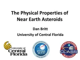
Introduction to NEOs and PHAs • Near-Earth object (NEO) is a solar system object whose orbit intersects with that of Earth. • All NEOs have a perihelion distance less than 1.3 AU • Potentially hazardous objects (PHAs) are NEOs that can be less than 0.05 AU from Earth and is at least 150 m • Many studies have gone into deflection of such bodies away from Earth Flyby of asteroid 2004 FH, closest miss ever noticed
Introduction to Mitigation Strategy • Short-term and long-term mitigation payload in addition to exploration mission • Reference mission to asteroid 99942 Apophis is the proof of concept for this process Apophis Exploration and Mitigation Platform LEO Flight Experiments Ground Experiments and Simulations
Apophis 99942 Background LL-chondrite composition Orbital period 323.6 days 7:8 Earth-Apophis orbit resonance Rotational period of 30.6 h Keyhole Event – April 13, 2029 Results in resonant return and possible impact in April 2036 Current impact probability: 1 in 250000 400 MT impact energy would yield regional destruction Largest bomb ever detonated was Tsar-Bomb (25 MT) Sources: “Apophis Risk Summary”, JPL NEO Program Chesley, Milani, Vokrouhlicky, Icarus 148, 118–138 (2000)
Why consider Apophis? • Apophis appears somewhat representative of the mid-range (~20 billion kg) of hazardous NEAs capable of causing regional destruction • Apophis is relatively easy to get to in the not-too-distant future • There are favorable, low energy launch windows every ~7yrs – coinciding with Apophis’ close approaches to Earth • We’ve missed the 2012-2014 window, but can still try for 2020-2022 • Although Apophis closely approaches Earth (esp. in 2029 and then in 2036) it is very unlikely to impact Earth • The Apophis mission is intended to be a “dress rehearsal,” not the “real thing.” • The aim is to flight-validate an archetypal exploration/mitigation operation • The 2021 – 2023 mission allows us to measurably change the orbit, verifying the technologies without producing significantly harmful orbit perturbations. • Once our technologies are proven, we can be ready for the real thing
AEMP: Mission Profile • Intermediate Analysis • Short Term Mitigation – Apr 2022 • Long Term Mitigation – May 2023 • Preliminary Analysis • Preliminary Exploration • Rendezvous – Sep 2021 • Cruise • Launch – Feb 2021 • Post Mitigation Investigation • End of Mission – Nov 2023
Long-Term Mitigation Technique: Altering Yarkovsky Effect Cooler “dawn” side Net force Solar Radiation hotter “dusk” side Excess radiation Carries away momentum Pphotonper photon D. Vokrouhlicky, A. Milani, and S. R. Chesley. “Yarkovsky Effect on Small Near-Earth Asteroids: Mathematical Formulation and Examples”, Icarus 148, 118-138 (2000).
Yarkovsky Effect • Yarkovsky effect is the result of anisotropic heating of a celestial object. • As the sunlit side of the asteroid rotates away from the sun, the warmer dusk side radiates more energy than on the cooler dawn side. • The resulting net force acts in a direction that is determined by the asteroid’s spin axis, rotation rate, and orbital period.
How to Modify the Yarkovsky Effect • Yarkovsky Effect is due to non-uniform thermal distribution of surface temperatures of asteroid. Option 1: Dump dirt Option 2: Change color Modify diurnal thermal wave indirectly by changing the albedo, the diffuse reflectivity, of the surface, which changes how many thermal photons are absorbed or reflected. Maximum O(.01 cm) is needed for opacity Modify diurnal thermal wave directly by depositing material on surface a depth of O(1 cm)
Efficacy of Albedo Change Apophis Trajectory Change from 2/14/2018 to 2/14/2036 Due to Changes in Energy Reflection, Absorption and Emission Giorgini, Benner, Ostro, Nolan, and Busch. Icarus 193 (2008) 1-19 • Two materials must be carried (light and dark) to account for orbit sensitivities due to spin axis orientation
AEMP: Surface Albedo Treatment System (SATS) 2023 NOV 2023 MAY • SATS raises or lowers the average albedo to produce a three-Earth-radii orbit deflection by 2036. • On the sun-facing side, the surface has a net positive charge. • The SATS nozzle is designed to impart a negative charge to the ACPs and dispensing is performed solely on the sun lit side. • This effect further ensures that the particles will be quickly bound to the surface and will not rebound or levitate into an escape condition. P. Lee, “Dust Levitation on Asteroids”, Icarus 124, 181-194 (1996)
AEMP: ACP Mass Calculation 2023 NOV 2023 MAY
Conservative Mass Calculation • Actually, only requires 0.5% of the surface to be modified. J. Giorgini, et al. “Predicting the Earth Encounters of (99942) Apophis”, Icarus 193: 1-19 (2008).
AEMP SATS Schematic 2023 NOV 2023 MAY A secondary flow is released into the outer portion of the selected ACP chamber The ACP storage chamber is double-walled; the ACPs being contained within the inner wall. The inner wall is perforated by many small holes. The gas flows through the holes in the inner wall, both “fluidizing” the ACP mass (mixing up the ACPs so that the dry powder behaves like a liquid) and expelling a steady stream of ACPs into the mixing chamber. Fluidization stream ACP Chamber Albedo Change Particles Pressurized Inert Gas Tribo ionization tube Mixing Chamber The main flow out of the gas supply leads directly to the mixing chamber. Once mixed, the ACPs plus gas is forced through the narrow tribo ionization tube
SATS Design • Tribo Ionization Tube • ACP Chamber (hopper system) • Valve Controller • Pressure Channels
Triboionization Tube • Static friction charging with particles gaining charge while traveling through a long tube of material with opposite electronegativity. • Requires pressurized gas to propel particles through tube. • Tribodispensers must be designed to optimize certain requirements.
Tribodispenser Schematic Modify tribo tube Modify hopper system *Based off Nordson Tribomatic 500
Tribo Tube: Component Changes *Based off Nordson Tribomatic 500
Tribo Tube: Model Choice • Ultimately, we chose Tribomatic 500 manufactured by Nordson because of • “Best” retrofitability • Lowest mass • Technical support personnel ability and willingness to help • Rigorous and detailed technical manuals • Proximity to Powder Coating Research Group
SATS Pressure Channels Dascalescu, Lucian. “Virtual Instrument for Statistic Control of Powder Tribo-charging Processes. “ Journal of Electrostatics Vol. 63: 565-570, 2005.
LEO Flight Experiments (LFE) • The Apophis Mitigation Technology LEO Flight Experiments (LFE) will demonstrate feasibility of an albedo changing prototype on a target surface in a controlled environment • Static Preliminary Albedo Demonstration Experiment (SPADE) design is a cube-shaped spacecraft 40x40x40 cm • Static, flat SATS test surface is part of satellite and exposed to LEO environment 2013 FEB 2012 DEC
LFE: SPADE Design Pressurant Gas Canister Powder Canister Torque Rod (3) Sun Sensor (4) Tribodispenser Tube Electronics Bay Batteries Antenna Camera Test Surface
Ground Experiments (GE) • Ground tests to determine optimal parameters for design of tribodispenserthrough repeated experiments with combinations of varying inputs. • Outputs to be maximized: • Charge-mass ratio (Q/M). This is immediately out of tube. will not be the same for each particle but we want the charge to be +/- 10-6 Coulombs (C) within 1 standard dev (σ). • Albedo Change (AC). Difference between albedo after treatment with albedo before treatment. This will mostly depend on the pigmentation of the powder. • Coverage area-mass ratio (A/M). • First pass transfer efficiency (FPTE). Mass of powder on surface over total mass after one trial. 2012 2010
Experimental Parameters • ASSUMED CONSTANTS: • Powder (developed by PCRG for our application) • Surface temperature (400K) • Surface roughness (distributed according to asteroid) • Surface material (LL Chondrite mod) • Surface charge (5 V) Secondary variables affecting the experiment are not shown! Comment: This chart only shows direct correlation. Obviously there’s indirect correlations as well. For instance, particles that have greater charge/mass ratio (Q/M) are more likely to “stick” to the surface and hence produce a larger albedo (AC).
Objective Hierarchy AHM: Note: All row entries are the number of times more important than column entries Weights: Albedo change is the most important objective criteria. Coverage area-mass ratio is the least important.
Optimization of Design • Conduct multiple runs of experiments with varying input parameters. • Obtain average and standard deviation of runs. • Give a measure of “goodness” to each output result (Q/M, AC, A/M, and FPTE) of each set of input parameters. • Multiply each “goodness” by the weights defined in objective hierarchy and sum them to obtain one number for each setup. The setup with the maximum number is the one to use.
Minimizing Experiment Runs • A full factorial experiment assuming two levels of factors, 2n runs are necessary where n is the number of independent parameters. • Using Taguchi methodology, this can be cut to 2(n+1) runs depending on number of considered interactions. • Orthogonal array/Taguchi Method assumes interactions between variables are negligible unless otherwise stated.
Experimental Trials D E L r ηm C B NOTE: For experiments not requiring all 8 factors here, simply ignore respective column in chart. Comment: e may be useful for error estimation Φ ηn F A G H ρinj ρdil ρvor
Determining Interrelationships • To find the optimal configuration, an equation can be written, Note: This is assuming a linear and quadratic term is sufficient for modeling. where yk = kth trial result of output (can be Q/M, albedo, FPTE, A/M) a = coefficients to be determined. Note that ai also applies to double coefficients xi = 1 (for maximum input value) or -1 (for minimum input value)
Experimental Trials • In addition to the 16 trials necessary, 3 repeated trials of conditions at the midpoint of the high and low levels for all 8 factors need to be conducted to find the errors • If errors are greater than data variation, more experiments have to be conducted and a more sophisticated equation model used
Experimental Schematic Lamp Faraday cage SATS Infrared heater Triboiontube of SATS Nozzle Aluminum plate Faraday cages Vacuum Chamber Electrometer Electrometers Gas Tank • Not shown: • - DAQ + Computers • Scale (to measure mass of SATS before and after each run as well as mass of plate before and after each run) • Cameras (to take photos of plate before and after each run for albedo and coverage area analysis AND flow) • Thermistors (measure temperature of plate)
Mounting Schematic Pipe Anchor Projector Hole Wedge Mount Tribodispenser Tube Side panel with slots for top surface to be placed on Top Surface Charged Surface Note: Actual setup needs to be vertical to simulate the condition of spraying onto an asteroid.
Environment Simulator • Vacuum chamber pressure is maintained at ultra-high vacuum of < O(10-5) Torr to simulate LEO environment (200 km altitude) • Solar lamp with wavelengths 300-4000 nm simulates solar radiation • Simulations in future will simulate degradation of ACPs through chemical reaction with atomic oxygen
Detector: Albedo Change • Nikon SLR camera has a wide depth of field to see all of surface area • Use Lambertian reflectance model knowing projector wavelength and intensity to predict reflected radiation. • Processed photons -> electrons -> voltage -> Gray scale intensity
Detector: Q/M Ratio • Optimal length for the tribo tube to pick up maximum charge • Multiple Faraday cages connected to electrometers along length of tube
Detector: FPTE and A/M • First pass transfer efficiency (FPTE) is ratio of powder deposited on coating target to amount of powder ejected from powder spray dispenser • Coverage area over mass (A/M) is found through two scale measurements of mass of surface (before and after deposition) and a camera/imaging algorithm to detect area
Surface • 0.22 m2 aluminum plate. • Necessary to confirm performance of simulation results of powder deposition. • Actual flight experiment has only one plate with roughness that varies along x-axis and albedo that varies along y-axis of plate. • Parameters to vary: • Roughness (ranging from perfectly smooth to very bumpy) • Albedo (ranging from pure white to pure black). • Charge • Other parameters (non-varying): • Temperature
Surface – 2D Test Bed • Eventually, Al surface will be replaced with surrogate asteroid surface.
Surface - 3D Design • A 3D model will be designed and constructed. Two routes: • Design 3D model in CAD and use CNC machine to construct model. Affix minerals afterwards. • Design and build wooden framework, wrap and staple flexible quarter inch wire around, and then apply plaster to wire for base surface. Affix minerals afterwards.
Powders: Requirements • Photoinitiators for curing to occur because energy is from radiation and not conduction. This is necessary for non-thermoset powders.* • Pigmentation for black and white powders. The right materials must be found to be compatible with photoinitiators. Will affect IR absorption (heat up) and albedo effect. • Rheology requirements. The powders must after melting, flow and harden. • Charge for powder is negative. Amount of charge also depends on several other factors aside from powder composition and size. There is a minimum charge required. Currently doing simulations. • Size of powder must be larger than a certain size, possibly 100 microns diameter**. Currently doing simulations.
Powder Interaction Thermal Conduction Absorber UV radiation Absorber Melts Cures Hardens IR Radiation Absorber Powder will have multiple materials that can perform different functions in the melting and curing process.
Powders: UV Curing • Material that can cure under UV radiation already exists. To formulate powder which can do so should not be a great technological leap. • A provisional patent can be filed within a week. • Choose materials based on solar UV radiation at LEO, solar IR radiation at LEO, and IR conduction of the surface. * Assuming black body with emissivity 1.
Powders: Pigments • Those materials that absorb or reflect too much radiation in the same bandwidth as photoinitiators will not allow photoinitiators to absorb enough energy. • Choose pigments for optimal IR absorption to heat powder and affect flow-out.
Pigmentation: Degradation • Primary causes of degradation on Earth • Water (moisture in air) • Oxygen (in air) • UV radiation (from sun) • Primary cause of degradation in space is just UV radiation. • With these materials, we can last for a while: • Black: Use calceine metal oxide. Can last ~20 years. • White: Titanium oxide encapsulated in an inert material. Last for >5 years.
Powders: Thickness Requirements • Enough thickness is necessary for opaqueness. An opaque coating completely covers a surface with color. • To achieve opaqueness, we require • Combination of an engineering of delivery device (Tribodispenser) and an optimal particle size distribution.* • A combination of large and small particles may be necessary for optimal packing.