ATLAS Luminometer
Explore the innovative front-end electronic system for the ATLAS Luminometer, aimed at measuring absolute luminosity of the ATLAS detector at the LHC. Detailed information on system components, testing procedures, and results presented at the TWEPP 2008 event.

ATLAS Luminometer
E N D
Presentation Transcript
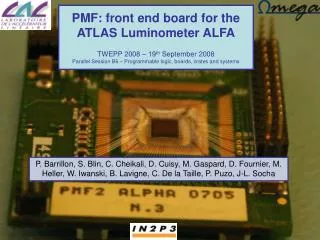
PMF: front end board for the ATLAS Luminometer ALFATWEPP 2008 – 19th September 2008 Parallel Session B6 – Programmable logic, boards, crates and systems P. Barrillon, S. Blin, C. Cheikali, D. Cuisy, M. Gaspard, D. Fournier, M. Heller, W. Iwanski, B. Lavigne, C. De la Taille, P. Puzo, J-L. Socha
ATLAS Luminometer • Goal: measure the absolute luminosity of ATLAS detector at the LHC looking at elastically diffused protons • ALFA (Absolute Luminosity For ATLAS) detector is made of 8 Roman Pots located at 240 m from the ATLAS interaction point. • Each RP is made of 20 layers (10 in U and 10 in V) of 64 scintillating fibers connected to a MAPMT. • The front end electronic is located in a matrix directly in the shadow of the PMs. Scintillating fibers in U/V diffused proton Beam TWEPP 2008 - B6 Session - P. Barrillon
Front end electronic The front end electronic is made of a matrix of 5x5 PMFs connected by lines of 5 to the mother board (or a test board) thanks to a kapton cable. Test board MOTHER BOARD or LUMI PM LUMI CABLE PMF = PhotoMultiplier Front-end PMF PMF PMF PMF PMF 5 4 3 2 1 PMF exploded view or active board lumi pmf2 alpha or passive board lumi pmf passive Big insulating Small insulating lumi pmf HV 0715 PMF Small insulating Big insulating PMT TWEPP 2008 - B6 Session - P. Barrillon
PMF structure • The PCB part of the PMF is made of 3 boards (3 × 3 cm2) : • HV board: allows bringing high voltage tot the MAPMT (64ch) • Passive board: roots signals to connectors on the edges of the board • Active board: readout and treatment of the PM output signals successively by the MAROC ASIC on one side and a Lattice FPGA on the other side. • A 60 points connector allows connection of the PMF with the mother board or the test board thanks to a kapton cable. • The 3 PCBs, the cable and the test board were developed at LAL, the mother board in Lund and the Lattice firmware at CERN. MAROC side Lattice side HV board Passive board Active board TWEPP 2008 - B6 Session - P. Barrillon
The active board • Challenging part of the project ! • Design of a 10 layers printed circuit board with MAROC chip bounded (at CERN) directly on the PCB on one side and a FPGA/BGA on the other side. • Different types of crossing vias • Limited space available for the other components (connectors, capacitors, resistors) and the test points. Top C2 TWEPP 2008 - B6 Session - P. Barrillon
MAROC description Hold signal 1 Hold signal 2 Multiplexed Analog charge output Variable Slow Shaper 20-100 ns S&H 1 MUX S&H 2 64 Wilkinson 12 bit ADC Photons Multiplexed Digital charge output 64 inputs Variable Gain Preamp. Bipolar Fast Shaper Photomultiplier 64 channels EN_serializer FS choice 64 trigger outputs Unipolar Fast Shaper Gain correction 64*6bits Cmd_LUCID 80 MHz encoder LUCID 3 discri thresholds (3*12 bits) 3 DACs 12 bits LUCID 9 Sums SUM of 7 fibres • Slow shaper • 2 Track & Hold (baseline and max) • Analog and digital multiplexed charge output • MAROC (Multi Anode ReadOut Chip) is a 64 ch ASIC which has a variable gain preamplifier and produces 64 trigger outputs and a multiplexed charge measurement. • Variable gain preamplifier (6 bits) • Super common base inputs: • Low impedance (50-100) tunable • Low bias current (20mA) • Thresholds set thanks to 10 bits DACs TWEPP 2008 - B6 Session - P. Barrillon
Laboratory tests of the first prototypes • The tests were carried out at LAL in collaboration with CERN • At first: development of both test board (Xilinx) and PMF (Lattice) FPGA firmwares as well as the test software. • Then: tests of the different PMF features (hits and charge measurements) with prototype couples passive/active boards Cable + active/passive board USB Test board Test software TWEPP 2008 - B6 Session - P. Barrillon
Results (prototype tests) Tests of 5 PMFs : • DAC linearity as satisfactory as for MAROC2 (< ± 1 %) • Homogeneous fast shaper pedestals (dispersion = 1 ‰) • Nice homogeneity of the s-curves • Cross talk at same level as MAROC2 (2-3 %) • Charge measurement: good linearity 1 PMF 314 ch/320 ok TWEPP 2008 - B6 Session - P. Barrillon
Tests with full PMF + LED • Tests carried out at CERN with a full PMF (PMT + 3 PCBs) and a LED lighting up a single channel or all of them. • The whole system works correctly and as expected. • Gain correction is efficient. Before gain correction: Mean = 37.5 % RMS = 4.9 Dispersion = 13.3 % Before gain correction: Mean = 35.8 % RMS = 1.3 Dispersion = 3.8 % TWEPP 2008 - B6 Session - P. Barrillon
Test beam preparation • 28 (23 needed) pre-series active, passive and HV boards were produced to equip a full roman pot together with the mother board • All active boards were tested (coupled with a passive board) at LAL before shipping to CERN and found ok for installation. 50% trigger Efficiency injected charge 28 boards DAC linearity Pedestals TWEPP 2008 - B6 Session - P. Barrillon
August 2008 beam tests Preliminary • Carried out at CERN. • Matrix of 23 PMFs readout by the last version of the mother board or 2 test boards (by group of 2×5 = 10 PMFs) • Offline analysis ongoing. Online one showed nice reconstruction of the beam position • All PMFs worked nicely as well as the kapton cables TWEPP 2008 - B6 Session - P. Barrillon
Conclusions • PMFs showed excellent performances with and without PMT • The group kapton cable + 5 PMFs works well • A nice homogeneity was observed between all PMFs tested • Just a few (7) channels cold or hot among 1792 tested • Protection of the ASIC with so-called jaja seems suitable • For the first a full matrix of 23 PMFs was tested with beam • Future: • Production of the 184 PMFs needed for the 8 final roman pots • Series test of the active boards produced TWEPP 2008 - B6 Session - P. Barrillon