Download

1 / 37
370 likes | 537 Vues
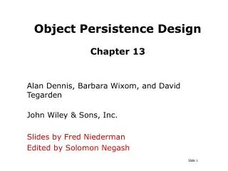
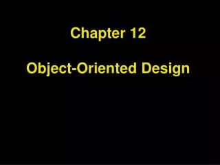
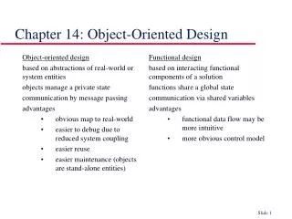
This section explores the object design problems that arise between application requirements and off-the-shelf components. It discusses how object design effectively bridges these gaps by defining custom objects for application needs. Key activities in object design, including UML activity diagrams and class diagrams, illustrate methods for defining behaviors and constraints for objects like the Hashtable class. Additionally, design principles such as invariants, preconditions, and postconditions are presented, culminating in an integrated approach to managing geographical information systems and emission modeling through user-centric visualizations.

E N D
Problem System Custom objects Application objects Solution objects Requirements gap Object design gap Off-the-shelf components System design gap Machine Figure 7-1. Object design closes the gap between application objects identified during requirements and off-the-shelf components selected during system design (stylized UML class diagram).
Figure 7-2. Activities of object design (UML activity diagram).
-numElements:int +put(key:Object,entry:Object) +get(key:Object):Object +remove(key:Object) +containsKey(key:Object):boolean +size():int Hashtable class Hashtable { private int numElements; /* Constructors omitted */ public void put (Object key, Object entry) {…}; public Object get(Object key) {…}; public void remove(Object key) {…}; public boolean containsKey(Object key) {…}; public int size() {…}; /* Other methods omitted */ } Figure 7-3. Declarations for the Hashtable class (UML class model and Java excerpts).
class Hashtable { /* The number of elements in the Hashtable is nonnegative at all times. * @inv numElements >= 0 */ private int numElements; /* The put operation assumes that the specified key is not used. * After the put operation is completed, the specified key can be used * to recover the entry with the get(key) operation: * @pre !containsKey(key) * @post containsKey(key) * @post get(key) == entry */ public void put (Object key, Object entry) {…}; /* The get operation assumes that the specified key corresponds to an * entry in the Hashtable. * @pre containsKey(key) */ public Object get(Object key) {…}; /* The remove operation assumes that the specified key exists in the * Hashtable. * @pre containsKey(key) * @post !containsKey(key) */ public void remove(Object key) {…}; /* Other methods omitted */ } Figure 7-4. Method declarations for the Hashtable class annotated with preconditions, postconditions, and invariants (Java, constraints in the iContract syntax [iContract]).
<<postcondition>> <<postcondition>> <<precondition>> <<precondition>> <<precondition>> <<invariant>> self.numElements >= 0 !containsKey(key) !containsKey(key) containsKey(key) containsKey(key) get(key) == entry HashTable numElements:int put(key,entry:Object) get(key):Object remove(key:Object) containsKey(key:Object):boolean size():int Figure 7-5. Examples of invariants, preconditions, and postconditions in OCL (UML class diagram).
New Session Layer fader Figure 7-6. Map with political boundaries and emission sources (JEWEL, mock-up).
Layer label WaterLayer RoadLayer PoliticalLayer * * * * Highway SecondaryRoad State County * * River Lake * * * * * * PolyLine Polygon Figure 7-7. Object model for the GIS of JEWEL (UML class diagram).
JEWEL GIS • Purpose • store and maintain the geographical information for JEWEL • Service • creation and deletion of geographical elements (roads, rivers, lakes, and boundaries) • organization of elements into layers • zooming (selection of points given a level of detail) • clipping (selection of points given a bounding box) Figure 7-9. Subsystem description for the GIS of JEWEL.
Displays geographical and emissions data to the user. Manages simulations and results. Manages GIS information for Visualization and EmissionsModeling. Engine for emission simulations. Maintains persistent data, including GIS and emissions data. Figure 7-10. Subsystem decomposition of JEWEL (UML class diagram).
Newly identifiedclass :Visualization :Layer :LayerElement :EndUser zoomIn(x,y) computeBoundingBox(x,y) *getOutline(r,d) *getOutline(r,d) points points Figure 7-11. A sequence diagram for the zoomIn() operation (UML sequence diagram). This sequence diagram leads to the identification of a new class, LayerElement. Because we are focusing on the GIS, we treat the Visualization subsystem as a single object.
Figure 7-12. Adding operations to the object model of the JEWEL GIS to realize zooming and clipping (UML class diagram).
High detail Low detail Two crossingroads Two neighboringcounties Figure 7-13. A naive point selection algorithm for the GIS. The left column represents a road crossing and two neighboring counties. The right column shows that road crossings and neighboring counties may be displayed incorrectly when points are not selected carefully.
Figure 7-14. Additional attributes and methods for the Point class to support intelligent point selection and zooming (UML class diagram).
Layer +label:String LayerElement +label:String +LayerElement(polyline:PolyLine) +getOutline(bbox:Rectangle2D, detail:double):Enumeration PolyLine +label:String +PolyLine() +getPoints():Enumeration -x, y:double -inDetailLevels:Set -notInDetailLevels:Set +Point(x, y:double) +includeInLevel(level:double) +excludeFromLevel(level:double) 1 +Layer(label:String) elements * +getOutline(bbox:Rectangle2D, detail:double):Enumeration 1 polyline 1 Point * points * Figure 7-15. Adding type information to the object model of the GIS (UML class diagram). Only selected classes shown for brevity.
Figure 7-16. Examples of preconditions and exceptions for the Layer class of the JEWEL GIS.
Figure 7-17. JFC components for the JEWEL Visualization subsystem (UML object diagram). Associations denote the containment hierarchy used for ordering the painting of components. We use stereotypes to distinguish JEWEL classes from classes provided by JFC.
// from java.awt package class Graphics { //... void drawPolyline(int[] xPoints, int[] yPoints, int nPoints) {…}; void drawPolygon(int[] xPoints, int[] yPoints, int nPoints) {…}; } Figure 7-18. Declaration for drawPolyline() and drawPolygon() operations [JFC, 1999].
Figure 7-19. An example of dynamic site with WebObjects (UML component diagram).
Figure 7-20. WebObject’s State Management Classes. The HTTP protocol is inherently stateless. The State Management Classes allow to maintain information between individual requests.
Figure 7-21. Realization of a unidirectional, one-to-one association (UML class diagram; arrow denotes the transformation of the object model).
Figure 7-22. Realization of a bidirectional one-to-one association (UML class diagram and Java excerpts; arrow denotes the transformation of the object design model).
class MapArea extends JPanel { private ZoomInAction zoomIn; /* Other methods omitted */ void setZoomInAction (action:ZoomInAction) { if (zoomIn != action) { zoomIn = action; zoomIn.setTargetMap(this); } } } class ZoomInAction extends AbstractAction { private MapArea targetMap; /* Other methods omitted */ void setTargetMap(map:MapArea) { if (targetMap != map) { targetMap = map; targetMap.setZoomInAction(this); } } } Figure 7-22 (continued from previous slide). Realization of a bidirectional one-to-one association (UML class diagram and Java excerpts; arrow denotes the transformation of the object design model).
Figure 7-23. Realization of a bidirectional, one-to-many association (UML class diagram; arrow denotes the transformation of the object design model).
Figure 7-24. Realization of a bidirectional, many-to-many association (UML class diagram; arrow denotes the transformation of the object design model).
Figure 7-25. Transformation of an association class into an object and two binary associations (UML class diagram; arrow denotes the transformation of the object design model). Once the model contains only binary associations, each association is realized by using reference attributes and collections of references.
Object design model before transformation * 0..1 SimulationRun Scenario simname Object design model after transformation Scenario SimulationRun -runs:Hashtable -scenarios:Vector +elements() +elements() +addRun(simname,sr:SimulationRun) +addScenario(s:Scenario) +removeRun(simname,sr:SimulationRun) +removeScenario(s:Scenario) Figure 7-26. Realization of a bidirectional qualified association (UML class diagram; arrow denotes the transformation of the object design model).
Figure 7-27. An example of code reuse with inheritance (UML class diagram).
Figure 7-28. AbstractFactory design pattern (UML class diagram, dependencies represent <<call>> relationships). This design pattern uses inheritance to support different look and feels (e.g., Motif and Macintosh). If a new specialization is added, the client does not need to be changed.
Figure 7-29. An example of implementation inheritance. The left column depicts a questionable implementation of MySet using implementation inheritance. The right column depicts an improved implementation using delegation. (UML class diagram and Java).
/* Implementation of MySet using inheritance */ class MySet extends Hashtable { /* Constructor omitted */ MySet() { } void insert(Object element) { if (this.get(element) == null){ this.put(element, this); } } boolean contains(Object element){ return (this.get(element)!=null); } /* Other methods omitted */ } /* Implementation of MySet using delegation */ class MySet { Hashtable table; MySet() { table = Hashtable(); } void insert(Object element) { if (table.get(element)==null){ table.put(element,this); } } boolean contains(Object element) { return (table.get(element) != null); } /* Other methods omitted */ } Figure 7-29 (continued from previous slide). An example of implementation inheritance. The left column depicts a questionable implementation of MySet using implementation inheritance. The right column depicts an improved implementation using delegation. (UML class diagram and Java).
Figure 7-30. Alternative representations of a unique identifier for a Person (UML class diagrams).
Figure 7-31. Delaying expensive computations using a Proxy pattern (UML class diagram).
Analysis Document Analysis model RAD analysis System design Subsystem Design goals decomposition Object design Initial object design model Figure 7-32. Embedded ODD approach. Class stubs are generated from the object design model. The object design model is then documented as tagged comments in the source code. The initial object design model is abandoned and the ODD is generated from the source code instead using a tool such as Javadoc (UML activity diagram, continued on next slide).
Object design Initial object design model Generate class stubs Initial class stubs Implementation Document Commented code ODD object design Figure 7-32 (continued from previous slide). Embedded ODD approach. Class stubs are generated from the object design model. The object design model is then documented as tagged comments in the source code. The initial object design model is abandoned and the ODD is generated from the source code instead using a tool such as Javadoc (UML activity diagram).
/* The class Layer is a container of LayerElements, each representing a * polygon or a polyline. For example, JEWEL typically has a road layer, a * water layer, a political layer, and an emissions layer. * @author John Smith * @version 0.1 * @see LayerElement * @see Point */ class Layer { /* Member variables, constructors, and other methods omitted */ Enumeration elements() {…}; /* The getOutline operation returns an enumeration of points representing * the layer elements at a specified detail level. The operation only * returns points contained within the rectangle bbox. * @param box The clipping rectangle in universal coordinates * @param detail Detail level (big numbers mean more detail) * @return A enumeration of points in universal coordinates. * @throws ZeroDetail * @throws ZeroBoundingBox * @pre detail > 0.0 and bbox.width > 0.0 and bbox.height > 0.0 * @post forall LayerElement le in this.elements() | * forall Point p in le.points() | * result.contains(p) */ Enumeration getOutline(Rectangle2D bbox, double detail) {…}; /* Other methods omitted */ } Figure 7-33. Interface description of the Layer class using Javadoc tagged comments (Java excerpts).
Figure 7-34.DetailTable is a global object tracking which Points have been included or excluded from a specified detailLevel. This is an alternative to the inDetailLevels and notInDetailLevels sets depicted in Figure 7-14.