Download
1 / 12
140 likes | 618 Vues
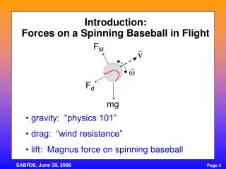
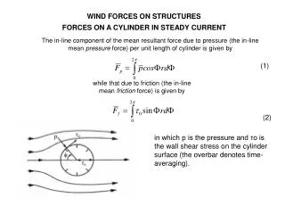
WIND FORCES ON STRUCTURES. FORCES ON A CYLINDER IN STEADY CURRENT. The in-line component of the mean resultant force due to pressure (the in-line mean pressure force) per unit length of cylinder is given by. (1). while that due to friction (the in-line mean friction force) is given by.

E N D
WIND FORCES ON STRUCTURES FORCES ON A CYLINDER IN STEADY CURRENT The in-line component of the mean resultant force due to pressure (the in-line mean pressure force) per unit length of cylinder is given by (1) while that due to friction (the in-line mean friction force) is given by (2) in which p is the pressure and τo is the wall shear stress on the cylinder surface (the overbar denotes time-averaging).
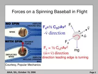
WIND FORCES ON STRUCTURES FORCES ON A CYLINDER IN STEADY CURRENT The total in-line force, the so-called mean drag, is the sum of these two forces: (3) Fp is termed the form drag and Ff the friction drag. Relative contribution of the friction force t the total drag for circular cylinder. For the range of Re numbers normally encountered in practice, namely Re ≥ 104, the contribution of the friction drag to the total drag forces is less than 2 – 3%. So the friction drag can be omitted in most of the cases, and the total mean drag can be assumed to be composed of only one component, namely the form drag.
WIND FORCES ON STRUCTURES FORCES ON A CYLINDER IN STEADY CURRENT Regarding the cross-flow component of the mean resultant force, this force will be nil’due to symmetry in the flow. However, the instantaneous cross-flow force on the cylinder, i.e., the instantaneous lift force, is non-zero and its value can be rather large. AERODYNAMIC COEFFICIENT: Pressure coefficient (4) where: po − static pressure ρ − flowing medium density U − inflow velocity
WIND FORCES ON STRUCTURES FORCES ON A CYLINDER IN STEADY CURRENT Mean drag coefficient (5) Mean lift coefficient (6) For the case of circular cylinder mean value FL = 0 due to symmetry of pressure distribution
WIND FORCES ON STRUCTURES FORCES ON A CYLINDER IN STEADY CURRENT Pressure cp distributions. S denotes the separtion point
WIND FORCES ON STRUCTURES FORCES ON A CYLINDER IN STEADY CURRENT Drag Coefficient as a Function of the Reynolds Number for a Smooth Sphere Dimpled Golf Ball: Reduce Drag the dimples of a golf ball (i.e., the surface roughness of the object) are used to create turbulent boundary layer flow, and hence reduce the drag force
WIND FORCES ON STRUCTURES FORCES ON A CYLINDER IN STEADY CURRENT
WIND FORCES ON STRUCTURES FORCES ON A CYLINDER IN STEADY CURRENT EFFECT OF REYNOLDS NUMBER Pressure distribution and wall shear stress distribution at different Re numbers for a smooth cylinder.
WIND FORCES ON STRUCTURES FORCES ON A CYLINDER IN STEADY CURRENT EFFECT OF SURFACE ROUGHNESS The drag coefficient, CD, now becomes not only a function of Re number but also a function of the roughness parameter ks/D (7) in which ks is the Nikuradse equivalent sand roughness. Drag coefficient of a circular cylinder for various surface roughness parameters ks/D.
WIND FORCES ON STRUCTURES FORCES ON A CYLINDER IN STEADY CURRENT EFFECT OF WALL PROXIMITY This topic is of direct relevance with regard to pipelines − what kind of changes take place in the flow around and in the forces on a pipe suspended above the bed with a small gap. Flow around a) free cylinder, b) a near-wall cylinder. S = separation points. 1.Vortex shedding is suppressed for the gap-ratio values smaller than about e/D = 0.3. 2. The stagnation point moves to a lower angular position. 3. The separation point at the free-stream side of the cylinder moves upstream and that at the wall-side moves downstream. 4. Suction is larger on the free-stream side of the cylinder than on the wall-side of the cylinder.
WIND FORCES ON STRUCTURES FORCES ON A CYLINDER IN STEADY CURRENT EFFECT OF WALL PROXIMITY Schematic variation of mean drag coefficient with the gap ratio. Variation of mean lift coefficient with the gap ratio.
WIND FORCES ON STRUCTURES EFFECT OF CROSS-SECTION SHAPE ON FORCE − COEFFICIENTS The shape of the cross-section has a large influence on the resulting force. There are two points, which need to be elaborated here. One is the Reynolds number dependence in the case of cross-sectional shapes with sharp edges. In this case, practically no Reynolds number dependence should be expected since the separation point is fixed at the sharp corners of the cross section. So, no change in force coefficients is expected with Re number for these cross-sections in contrast to what occurs in the case of circular crosssections. Secondly, non-circular cross-sections may be subject to steady lift at a certain angle of attack. This is due to the asymmetry of the flow with respect to the principle axis of the cross-sectional area.