Download
1 / 25
250 likes | 451 Vues
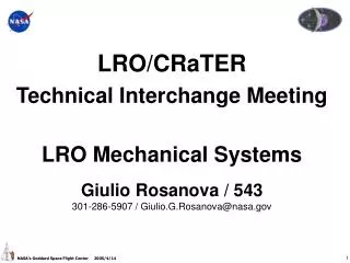
LRO/CRaTER Technical Interchange Meeting LRO Mechanical Systems Giulio Rosanova / 543 301-286-5907 / Giulio.G.Rosanova@nasa.gov. X (Thrust). Y. Z (NADIR). LRO Baseline (Deployed 0n Orbit). High Gain Antenna. IM Optical Bench /Radiator. Avionics Module. Propulsion Module.

E N D
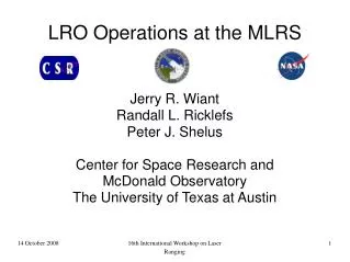
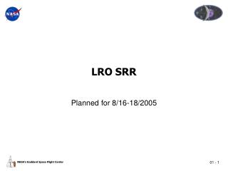
LRO/CRaTER Technical Interchange Meeting LRO Mechanical Systems Giulio Rosanova / 543 301-286-5907 / Giulio.G.Rosanova@nasa.gov
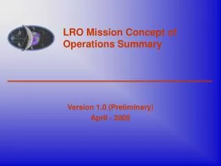
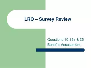
X (Thrust) Y Z (NADIR) LRO Baseline (Deployed 0n Orbit) High Gain Antenna IM Optical Bench /Radiator Avionics Module Propulsion Module Solar Array
LRO Baseline (Deployed on Orbit) Optical Bench / Radiator Instrument Module Solar Array Avionics Module Propulsion Module High Gain Antenna X (Thrust) Z (NADIR) Y
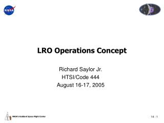
LRO Baseline (Stowed) High Gain Antenna Instrument Module Avionics Module Propulsion Module Solar Array
INSTRUMENTS CRaTER Diviner LAMP LEND LOLA LROC HIGH GAIN ANTENNA SYST PROPULSION MODULE SOLAR ARRAY SYSTEM INSTRUMENT MODULE AVIONICS MODULE Propulsion Electrical Mechanical Thermal HGA Dish Deployables Gimbals Boom Electrical Mechanical Thermal Electrical Mechanical Thermal Solar Cells Substrate Deployables Gimbals Boom LRO Nomenclature ORBITER SPACECRAFT SPACECRAFT BUS
LRO Coordinate System Definition ZENITH (-Z) Coordinate Axis Origin Located at center of L/V Separation Plane RHR (+Y) THRUST DIRECTION (+X) Velocity Vector +/- X axis NADIR (+Z)
Mechanical Baseline Design 79 in. (2.0 m) 82 in. (2.1 m) 110 in. (2.8 m)
LRO Launch Vehicle Interface DELTA-II 3-Stage 9.5 ft. P/L Envelope 100” DIA. (2.54m)
Mechanical System Requirements • Mechanically Accommodate LRO Instrument Suite • Provide Mechanically Stable Instrument Bench for Pointing Requirements • Meet Instrument FOV Requirements • Provide Thermal Radiator Area for Instruments • Provide Orbiter Purge System for Instruments • Compatibility with DELTA-II Class Launch Vehicle • Instruments shall comply with “LRO Structural Loads and Mechanical Environments Specification” (430-SPEC-000022) • Fairing Doors for Instrument Access on Launch Pad • T-0 Purge Available
Mechanical System Requirements • Comply with LRO Alignment, Pointing Jitter Budget • Instrument Pointing/Alignment Errors • Thermal Distortion after Off-Pointing and/or Eclipse, G-Sag • High Frequency Jitter • Deployed Structures First deployed Frequency: ≥1 Hz • Verify all Mechanical / Structural Designs and Functionality • Qualification by Test • Use Simulators to Verify Interfaces • Provide Orbiter Wiring Mock-Up • Instrumenters to provide Hi-Fi Mass simulators for complex Designs • Used for LRO Orbiter Structural Qualification Testing
Instrument Design Requirements • Design Limit Load: 12 g’s any axis • Minimum Factors of Safety • Minimum Frequency Requirement: 35 Hz (50 Hz Recommended) • Overall acoustic environment: 149.6 dB qual, 146.6 dB acceptance • Random Vibration Environment for Instruments and Components
LRO FEM: Configuration F **Total Mass: 2490 lbm (1129 kg) **CG (Origin at center of clampband IF) **Mass Moments of Inertia
Fundamental Mode: Lateral Direction **Mass scaled to launch vehicle capability (1480 kg) fn = 19.9 Hz fn = 19.6 Hz
Fundamental Mode: IM fn = 46 Hz
Mechanical Topics for TIM • CAD Models: (PRO-Engineer), (SOLID-WORKS), (IDEAS) • Identify CRaTER Orientation wrt LRO Coordinate System • Identify Access zones to support testing do you Require? • (i.e., sources required for calibration, etc) • Identify Connector Locations and Access/Stay-Out Zones Required? • Identify Optical Reference Surfaces (as required)? • Alignment cube/reference mirror surfaces: size, and location? • Identify GSE Handling Points • Will Aperture Doors or Shutter be Considered? • FEA Models: (FEMAP), (NASTRAN)
Mechanical Topics for TIM • Identify your Design Heritage? (have some MLA info) • What were the design limit loads? • What factors of safety were used? • What was the random vibration environment? • What was the instrument’s first frequency ? • What Analysis Documentation Exists? • What Verification Test Reports Exist? • Is the instrument sensitive to shock or acoustics? • Do you require Access while on the Launch Pad? • Do you require T-0 Purge at Launch? • Mechanical Mass Simulator Required • Simple Designs over 50 Hertz (i.e. LAMP, CRaTER) mass and CG only. • Mass Simulator must be Qualified before Orbiter Structural Testing.
CDR LRO Mechanical System Development Flow INSTRUMENT MASS SIMS. MECHANICAL Design & Analysis PROP. Module (PTyp) Build 12/06 S/C Bus (PFlt) Build Mechanical System Assy. Functional Mechanical Qualification Testing 1/07 12/06 9/06 Inst. Module (PFlt) Build 4/06 INSTRUMENTS Deployables (PFlt) Build & Test 7/07 MECHANICAL Fabrication 10/07 PM Pluming Assy. Spacecraft I&T Orbiter I&T PROP. Module (FLT) Build & Proof 10/06 4/07 10/07 9/06 2/08 1/07 Orbiter Environmental Testing LRO S/C Subsystems / Components 7/08 Launch Activities LRD 10/08