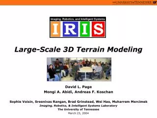
3D Graphics Rendering and Terrain Modeling
3D Graphics Rendering and Terrain Modeling. Technology and Historical Overview. By Ricardo Veguilla. Overview. Introduction to 3D Computer Graphics OpenGL SGI vs Linux 3D Animation Terrain Modeler: Project Status . Introduction to 3d Computer Graphics.

3D Graphics Rendering and Terrain Modeling
E N D
Presentation Transcript
3D Graphics Rendering and Terrain Modeling Technology and Historical Overview By Ricardo Veguilla
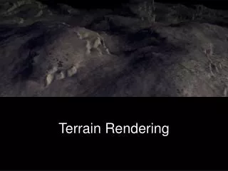
Overview • Introduction to 3D Computer Graphics • OpenGL • SGI vs Linux • 3D Animation • Terrain Modeler: Project Status
Introduction to 3d Computer Graphics • 3D computer graphics is the science, study, and method of projecting a mathematical representation of 3D objects onto a 2D image using visual tricks such as perspective and shading to simulate the eye's perception of those objects.
3D Graphics and Physics • 3D graphic software is largely based on simulating physical interactions. • Generally: • Space relations. • Light interactions. • In particular cases: • Material properties. • Object Movement.
Goals of 3D computers graphics • Practical goal: Visualization - to generate images (usually of recognizable subjects) that are useful in some way. • Ideal goal: Photorealism - to produce images indistinguishable from photographs.
Components of a 3D Graphic System • 3D Modeling: • A way to describe the 3D world or scene, which is composed of mathematical representations of 3D objects called models. • 3D Rendering: • A mechanism responsible for producing a 2D image from 3D models.
3D Modeling • Simple 3D objects can be modeled using mathematical equations operating in the 3-dimensional Cartesian coordinate system. • Example: the equation x2 + y2 + z2 = r2 is a model of a perfect sphere with radius r.
Modeling considerations • Pure mathematical equations to represent 3D objects requires a great deal of computing power • Impractical for real-time applications such as games or interactive simulations.
Alternatives: Polygon Models • Modeling objects by sampling only certain points on the object, retaining no data about the curvature in between • More efficient, but less detailed.
Alternatives: Texture Mapping • Technique used to add surface color detail without increasing the complexity of a model. • An image is mapped to the surface of a model.
From 3D models to 2D images • A 3D world or scene is composed of collection of 3d models • Three different coordinates systems (or spaces) are defined for different model related operations: • Object Space • World Space • Screen Space
Object Space • The coordinate system in which a specific 3D object is defined. • Each object usually have its own object space with the origin at the object's center • The object center is the point about which the object is moved and rotated.
World Space • World space is the coordinate system of the 3D world to be rendered. • The position and orientation of all the models are defined relative to the center of the world space. • The position and orientation of the virtual camera is also defined relative to the world space.
Screen Space • 2D space that represents the boundaries of the image to be produced. • Many optimization techniques are performed on screen space.
Mathematics of 3D graphics • 3D operations like translation, rotation and scaling are performed using matrices and lineal algebra. • Each operation is performed by multiplying the 3D vertices by a specific transformation matrix.
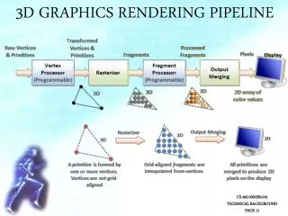
3D Rendering • The process of taking the mathematical model of the world and producing the output image. • The core of the rendering process involves projecting the 3D models onto a 2D image plane.
Types of Rendering Algorithms • Two general approaches: • Pixel-oriented rendering: • Ray tracers • Polygon-oriented rendering: • Scan-line renderers
Ray tracers • Operates by tracing theoretical light rays as they intersect objects in the scene and the projection plane.
Ray tracer limitations • Processor intensive. A full ray tracer is impractical for real-time applications. • Does not take into account inter-reflections of diffuse light, resulting in hard shadows.
Radiosity • Technique that models the inter-reflections of diffuse light between surfaces of the world or environment. • Produces more photorealistic illumination and shadows.
Scan-line renderers • Operate on an object-by-object basis, directly drawing each polygon to the screen. • Requires all objects – including those modeled with continuous curvature – to be tessellated into polygons. • Polygons are eventually tessellated into pixels.
Illumination for scan-line renderers • Lighting and shading is calculated using the normal vector. • The color is linearly interpolated across the polygon surface.
Common shading techniques scan-line renderer • Flat shading • Gouraud Shading • Phong Shading
Flat Shading • The color of the polygon is calculated at the center of the polygon by using the normal vector. • The complete polygon surface is uniformly lighted.
Gouraud Shading • A normal vector is calculated at each vertex. • Color is calculated for each vertex and interpolated across the polygon
Phong Shading • The normal vectors are interpolated across the surface of the polygon • The color of each point within the polygon is calculated from its corresponding normal vector
Viewing frustum • Segment of the 3D world to be rendered • Objects outside the viewing volume are ignored.
Hidden surface determination • Not all objects inside the viewing frustum are always visible from the point of view of the camera. • Not all polygons of a particular object are visible from the point of view of the camera. • Common Techniques • Painters Algorithm • Z-Buffering
Painter’s Algorithm • Polygon-oriented. • All the polygons are sorted by their depth and then displayed in this order.
Z-Buffering • Pixel-oriented. • When multiple objects overlap (from the point of view of the camera) on a particular pixel, only the value of the pixel closest to the camera is used. • Implemented by saving the depth value of each displayed pixel in a buffer, and comparing the depth of each new overlapping pixel against the value in the buffer.
Perspective Projection • Projects the 3D world to a 2D image
References: • Wikipidia – The Free Encyclopedia • http://www.wikipedia.org/ • OpenGL - The Industry Standard for High Performance Graphics • http://www.opengl.org/ • Google Image Search • http://images.google.com • Overview of 3D Interactive Graphics • http://www.siggraph.org/project-grants/com97/com97-tut.html • Linux Journal - Industry of Change: Linux Storms Hollywood • http://www.linuxjournal.com/article/5472 • JCanyon - Grand Canyon Demo • http://java.sun.com/products/jfc/tsc/articles/jcanyon/