3D Graphics Rendering Pipeline
3D Graphics Rendering Pipeline. CS 490.006/582.001 Technical Background Page 11. Coordinates Transformation.
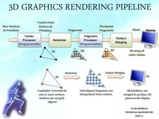

3D Graphics Rendering Pipeline
E N D
Presentation Transcript
3D Graphics Rendering Pipeline CS 490.006/582.001 Technical Background Page 11
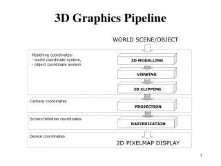
Coordinates Transformation Objects are typically created in their local spaces. We need to bring them into the common world space, via a series of affine transformations (translation, rotation, and scaling). Camera is defined via view parameters EYE, AT, and UP, measured in world space. It is located at EYE, pointing at AT, with upward orientation of UP. In the camera space, the camera is located at the origin, pointing at –zc, with upward orientation of yc, where zc is opposite of AT and yc is roughly UP. CS 490.006/582.001 Technical Background Page 12
Coordinates Transformation The camera’s view frustum is defined via a perspective projection using 4 view parameters: fovy (the total vertical angle of view), aspect (the ratio of width vs. height), zNear (the near plane), and zFar (the far plane). A projection matrix is applied to transform the view frustum into an axis-aligned cuboid clipping volume of 2x2x1 centered on the near plane (at z=0) with the far plane (after flipping) at z=1. The planes have dimensions of 2x2, with range from -1 to +1. CS 490.006/582.001 Technical Background Page 13
Lighting CS 490.006/582.001 Technical Background Page 14
Texture Filtering CS 490.006/582.001 Technical Background Page 15
Geometry Shaders CS 490.006/582.001 Technical Background Page 16
Tessellation Shaders CS 490.006/582.001 Technical Background Page 17
Orientation Representation Animating continuous reorientations of traditional Euler angles produces strange discontinuities and apparent reversals in the accumulated motion, as illustrated with “gimbal lock”. CS 490.006/582.001 Technical Background Page 18
Linear Skinning In traditional linear skinning, meshes are bound to skeletons by binding each mesh vertex to one or more bones, maintaining their position relative to the moving bones during animation. When a joint bends, mesh vertices that are attached to both bones are repositioned at the average location between where they would be placed if attached to only one bone. This produces an undesired collapsing and pinching effect at the joint. CS 490.006/582.001 Technical Background Page 19
Dual Quaternion Skinning By blending the vertices rotationally instead of linearly, a vertex that is weighted half towards one bone and half towards another does not collapse towards the joint. While this avoids the shrinkage associated with linear skinning, rotational blending does cause the bent area to inflate a bit, with an overly smooth pinch on the inside of the fold. Adjusting the weighting of the different bones and altering the vertex density of the mesh can address this problem. CS 490.006/582.001 Technical Background Page 20