Rendering Pipeline
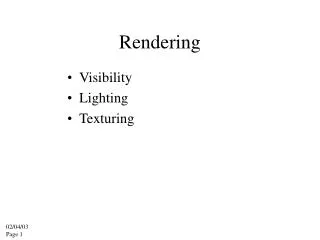
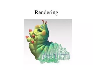
Rendering Pipeline. Fall, 2011. 3D Polygon Rendering. Many applications use rendering of 3D polygons with direct illumination. 3D Polygon Rendering. What steps are necessary to utilize spatial coherence while drawing these polygons into a 2D image?.

Rendering Pipeline
E N D
Presentation Transcript
Rendering Pipeline Fall, 2011
3D Polygon Rendering • Many applications use rendering of 3D polygons with direct illumination
3D Polygon Rendering • What steps are necessary to utilize spatial coherence while drawing these polygons into a 2D image?
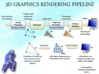
3D Rendering Pipeline (for direct illumination) Transform into 3D world coordinate system Illuminate according to lighting and reflection Transform into 3D camera coordinate system Transform into 2D camera coordinate system Clip primitives outside camera’s view Transform into image coordinate system Draw pixels (includes texturing, hidden surface, …)
Viewing Transformation • Mapping from world to camera coordinates • Eye position maps to origin • Right vector maps to X axis • Up vector maps to Y axis • Back vector maps to Z axis Y X World Z
Camera Coordinates • Canonical coordinate system • Convention is right-handed(looking down –z axis) • Convenient for projection, clipping, etc .
Finding the viewing transformation • We have the camera (in world coordinates) • We want T taking objects from world to camera • Trick: find T-1 taking objects in camera to world
Finding the viewing transformation • Trick: map from camera coordinate to world • Origin maps to eye position • Z axis maps to Back vector • Y axis maps to Up vector • X axis maps to Right vector • This matrix is T-1 so we invert in to get T (easy)
Projection • General definition: • Transform points in n-space to m-space (m<n) • In computer Graphics: • Map 3D camera coordinates to 2D screen coordinates
Parallel Projection • Center of projections is at infinity • Direction of projection (DOP) same for all points
Orthogonal Projections • DOP perpendicular to view plane
perpendicular angle Oblique angle Oblique Projections • DOP not perpendicular to view plane 1) Cavalier projection • when angle between projector and view plane is 45 degree • foreshortening ratio for all three principal axis are equal. 2) Cabinet projection • the foreshortening ratio for edges that perpendicular to the plane of projection is one-half (angle 63.43 degree )
Oblique Projections • DOP not perpendicular to view plane
Parallel Projection Matrix • General parallel projection transformation
Perspective Projection • Map points onto “view plane” along “projectors” emanating from “center of projection” (COP)
Perspective Projection • How many vanishing points?
Perspective Projection • Compute 2D coordinates from 3D coordinates with similar triangles
Perspective Projection Matrix • 4 x 4 matrix representation?
Perspective Projection Matrix • 4 x 4 matrix representation?
Perspective vs. Parallel • Parallel Projection + Good for exact measurements + Parallel lines remain parallel • Angles are not (in general) preserved • Less realistic looking • Perspective Projection + Size varies inversely with distance – looks realistic • Distance and angles are not (in general) preserved • Parallel line do not (in general) remain parallel
Viewing Transformations Summary • Camera Transformation • Map 3D world coordinates to 3D camera coordinates • Matrix has camera vectors are rows • Projection Transformation • Map 3D camera coordinates to 2D screen coordinates • Two type of projections • Parallel • Perspective
2D Rendering Pipeline Clip portions of geometric primitives residing outside the window Transform the clipped primitives From screen to image coordinates Fill pixels representing primitives In screen coordinates
Clipping • Avoid drawing parts of primitives outside window • Window defines part of scene being viewed • Must draw geometric primitives only inside window
Clipping • Avoid drawing parts of primitives outside window • Points • Lines • Polygons • Circles • etc.
Point Clipping • Is point (x, y) inside window?
Line Clipping • Find the part of a line inside the clip window
Cohen Sutherland Line Clipping • Use simple tests to classify easy cases first
Cohen Sutherland Line Clipping • Classify some lines quickly AND of bit codes representing regions of two end points (must be 0)
Cohen Sutherland Line Clipping • Compute intersections with window boundary for lines that can’t be classified quickly
Cohen Sutherland Line Clipping • Compute intersections with window boundary for lines that can’t be classified quickly
Cohen Sutherland Line Clipping • Compute intersections with window boundary for lines that can’t be classified quickly
Polygon Clipping • Find the part of a polygon inside the clip window?
Sutherland Hodgeman Clipping • Clip each window boundary one at a time
Clipping to a Boundary • Do inside test for each point in sequence, • Insert new points when cross window boundary, • Remove Points outside window boundary
2D Rendering Pipeline Clip portions of geometric primitives residing outside the window Transform the clipped primitives From screen to image coordinates Fill pixels representing primitives In screen coordinates
Viewport Transformation • Transformation 2D geometric primitives from screen coordinate system (normalized device coordinates) to image coordinate system (pixels)
Viewport Transformation • Window-to-Viewport mapping