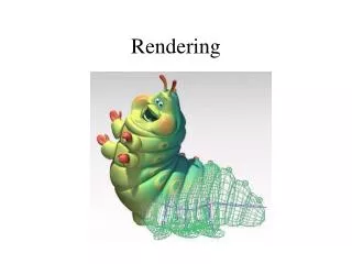
Rendering Pipeline
Rendering Pipeline. Aaron Bloomfield CS 445: Introduction to Graphics Fall 2006 (Slide set originally by Greg Humphreys). 3D Polygon Rendering. Many applications use rendering of 3D polygons with direct illumination. 3D Polygon Rendering.

Rendering Pipeline
E N D
Presentation Transcript
Rendering Pipeline Aaron Bloomfield CS 445: Introduction to Graphics Fall 2006 (Slide set originally by Greg Humphreys)
3D Polygon Rendering • Many applications use rendering of 3D polygonswith direct illumination
3D Polygon Rendering • Many applications use rendering of 3D polygonswith direct illumination Quake II (Id Software)
3D Polygon Rendering • Many applications use rendering of 3D polygonswith direct illumination
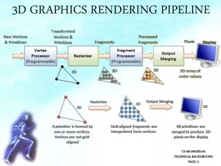
3D Rendering Pipeline 3D Geometric Primitives Modeling Transformation Lighting This is a pipelined sequence of operations to draw a 3D primitive into a 2D image (this pipeline applies only for direct illumination) Viewing Transformation Projection Transformation Clipping Scan Conversion Image
Example: OpenGL Modeling Transformation glBegin(GL_POLYGON); glVertex3f(0.0, 0.0, 0.0); glVertex3f(1.0, 0.0, 0.0); glVertex3f(1.0, 1.0, 1.0); glVertex3f(0.0, 1.0, 1.0); glEnd(); Viewing Transformation Lighting & Texturing Projection Transformation OpenGL executes steps of 3D rendering pipeline for each polygon Clipping Scan Conversion Image
3D Rendering Pipeline 3D Geometric Primitives Modeling Transformation Transform into 3D world coordinate system Viewing Transformation Lighting & Texturing Projection Transformation Clipping Scan Conversion Image
3D Rendering Pipeline 3D Geometric Primitives Modeling Transformation Transform into 3D world coordinate system Transform into 3D camera coordinate system Done with modeling transformation Viewing Transformation Lighting & Texturing Projection Transformation Clipping Scan Conversion Image
3D Rendering Pipeline 3D Geometric Primitives Modeling Transformation Transform into 3D world coordinate system Transform into 3D camera coordinate system Done with modeling transformation Viewing Transformation Illuminate according to lighting and reflectance Apply texture maps Lighting & Texturing Projection Transformation Clipping Scan Conversion Image
3D Rendering Pipeline 3D Geometric Primitives Modeling Transformation Transform into 3D world coordinate system Transform into 3D camera coordinate system Done with modeling transformation Viewing Transformation Illuminate according to lighting and reflectance Apply texture maps Lighting & Texturing Projection Transformation Transform into 2D screen coordinate system Clipping Scan Conversion Image
3D Rendering Pipeline 3D Geometric Primitives Modeling Transformation Transform into 3D world coordinate system Transform into 3D camera coordinate system Done with modeling transformation Viewing Transformation Illuminate according to lighting and reflectance Apply texture maps Lighting & Texturing Projection Transformation Transform into 2D screen coordinate system Clipping Clip primitives outside camera’s view Scan Conversion Image
3D Rendering Pipeline 3D Geometric Primitives Modeling Transformation Transform into 3D world coordinate system Transform into 3D camera coordinate system Done with modeling transformation Viewing Transformation Illuminate according to lighting and reflectance Apply texture maps Lighting & Texturing Projection Transformation Transform into 2D screen coordinate system Clipping Clip primitives outside camera’s view Scan Conversion Draw pixels (includes texturing, hidden surface, ...) Image
Camera Coordinates • Canonical coordinate system • Convention is right-handed (looking down -z axis) • Convenient for projection, clipping, etc. Camera up vector maps to Y axis y Camera right vector maps to X axis Camera back vector maps to Z axis (pointing out of screen) z x
z y x World Viewing Transformation • Mapping from world to camera coordinates • Eye position maps to origin • Right vector maps to X axis • Up vector maps to Y axis • Back vector maps to Z axis back up right View plane Camera
Viewing Transformations p(x,y,z) 3D Object Coordinates Modeling Transformation 3D World Coordinates Viewing Transformation Viewing Transformations 3D Camera Coordinates Projection Transformation 2D Screen Coordinates Window-to-Viewport Transformation 2D Image Coordinates p’(x’,y’)
Projection • General definition: • Transform points in n-space to m-space (m<n) • In computer graphics: • Map 3D camera coordinates to 2D screen coordinates • For perspective transformations, no two “rays” are parallel to each other
Taxonomy of Projections FVFHP Figure 6.10
Parallel Projection • Center of projection is at infinity • Direction of projection (DOP) same for all points DOP View Plane Angel Figure 5.4
Orthographic Projections • DOP perpendicular to view plane Front Top Side Angel Figure 5.5
Oblique Projections • DOP not perpendicular to view plane Cavalier (DOP = 45o) Cabinet (DOP = 63.4o) H&B Figure 12.24
Parallel Projection View Volume H&B Figure 12.30
Parallel Projection Matrix • General parallel projection transformation:
Taxonomy of Projections FVFHP Figure 6.10
Perspective Projection • Map points onto “view plane” along “projectors” emanating from “center of projection” (COP) Projectors Center of Projection View Plane Angel Figure 5.9
3-Point Perspective 2-Point Perspective 1-Point Perspective Perspective Projection • How many vanishing points? • The difference is how many of the three principle directions are parallel/orthogonal to the projection plane Angel Figure 5.10
Perspective Projection View Volume View Plane H&B Figure 12.30
Camera to Screen • Remember: Object Camera Screen • Just like raytracer • “screen” is the z=d plane for some constant d • Origin of screen coordinates is (0,0,d) • Its x and y axes are parallel to the x and y axes of the eye coordinate system • All these coordinates are in camera space now
Overhead View of Our Screen Yeah, similar triangles!
The Perspective Matrix • This “division by z” can be accomplished by a 4x4 matrix too! • What happens to the point (x,y,z,1)? • What point is this in non-homogeneous coordinates?
Taxonomy of Projections FVFHP Figure 6.10
Perspective vs. Parallel • Perspective projection • Size varies inversely with distance - looks realistic • Distance and angles are not (in general) preserved • Parallel lines do not (in general) remain parallel • Parallel projection • Good for exact measurements • Parallel lines remain parallel • Angles are not (in general) preserved • Less realistic looking
Classical Projections Angel Figure 5.3
Viewing in OpenGL • OpenGL has multiple matrix stacks – trans-formation functions right-multiply the top of the stack • Two most important stacks: GL_MODELVIEW and GL_PROJECTION • Points get multiplied by the modelview matrix first, and then the projection matrix • GL_MODELVIEW: Object->Camera • GL_PROJECTION: Camera->Screen • glViewport(0,0,w,h): Screen->Device
Summary • Camera transformation • Map 3D world coordinates to 3D camera coordinates • Matrix has camera vectors as columns • Projection transformation • Map 3D camera coordinates to 2D screen coordinates • Two types of projections: • Parallel • Perspective