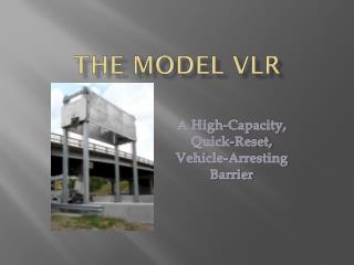
The Model VLR
The Model VLR. A High-Capacity, Quick-Reset, Vehicle-Arresting Barrier. Company Background. B&B Roadway traces it’s origins back to 1926.

The Model VLR
E N D
Presentation Transcript
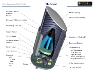
The Model VLR A High-Capacity, Quick-Reset, Vehicle-Arresting Barrier
Company Background B&B Roadway traces it’s origins back to 1926. Specialize in traffic control gates and barriers for various highway and bridge applications including movable bridges, HOV access control, weather closure, reversible lane, and emergency or multi-purpose ingress/egress control Have developed a number of types of gates and barriers pinpointed to the needs of these applications and regularly customize or custom-design products for specific applications
Over the Years, Things Change • Safety consciousness • Public demand for safer transportation designs • Traffic management designs and plans • Technology • Ever-increasing traffic load > innovative traffic management techniques
Changes In Public Expectations • SAFETY • The Public (and transportation managers/owners) want safer, gentler methods of traffic control • CAPACITY • Stop more vehicles, more of the time • SHORT DOWN TIME • Low tolerance for long down times
Objectives • Higher Energy Absorption Capacity • Softer, Safer Stop • Rapid Re-Set/Repair After a Collision • Predictable Post-Collision Replacement Parts • Adjustability
Capacity E = ½ mv2 (Kinetic Energy Formula) Energy is proportional to mass times velocity squared. Heavier vehicles and/or faster speeds increases the energy to be absorbed. The same vehicle at 60mph has 44% more energy than at 50mph (20% increase in velocity)
Safety • Keep G-forces low • Control the vehicle trajectory • Minimize damage to the vehicle
Quick Re-Set Typical barrier systems take hours or days (even weeks, if parts have to be ordered) to have the barrier back in working condition after a collision. This is expensive and compromises safety. Keys to quick re-set are predictable replacement parts and a simple replacement procedure.
Predictable Replacement Parts • Ensures the right parts are on hand and minimizes stocking a multitude of “just-in-case” components • Takes the guess work out of “what do we need to replace ?” • Makes down time predictable and consistent • Reduces degree of expertise in re-setting the barrier – can easily train service personnel
Simple Replacement Procedure • A few, simple tools – no extensive, bulky equipment • Minimal connections and adjustments • Minimal manpower • Fairly obvious procedure
Adjustability Allows barrier to adapt to varied customer requirements: • Short / long run-out distances • High average speeds / low average speeds • Heavier / lighter typical traffic (commercial traffic versus commuter traffic)
Objectives (Review) • High Energy Absorption Capacity • Soft, Safe Stop • Rapid Re-Set/Repair After a Collision • Predictable Replacement Parts & Simple Procedure • Adjustability
Problem #1: Capacity • How to fit the amount of holding power we needed into a small package? • Several years ago, unable to find a commercially available torque-limiter with the high capacity we required in a small enough package, we developed our own for use in another barrier • Could an adaptation of this basic design, used as a brake to pay out a strap, provide enough capacity?
Capacity Calculations Capacity calculations showed that the brake could absorb well over 1,000,000 ft-lb of energy • 2,000 lb vehicle (small passenger car) at 60mph is 240,000 ft-lb kinetic energy • 4,400 lb vehicle (pickup truck) at 60mph is 529,000 ft-lb energy • 10,000 lb vehicle (commercial truck) at 60mph is 1,200,000 ft-lb energy By adjusting the pressure on the brake, can achieve a desirable range of capacities (Bonus: Adjustability objective is achieved)
Problem #2 : G-forces • Longer payout distances produce lower G-forces and vice versa • Since energy = force x distance, by adjusting the torque setting of the brake, various payout distances could be achieved for absorbing a given amount of vehicle energy • Calculations showed that a “typical” brake setting would produce quite low G arrests
Design Stage 1and Proof-of-Concept Test In order to verify the basic concept, we conducted preliminary tests at our own facility
Initial Test Results • Tests verified the concept • Results closely matched calculations … Ready to move on to the next design stage!
Problem #3 : “Catching”the Vehicle • Wide range of vehicle profiles • How to securely retain the vehicle while minimizing damage
Catching the Vehicle • Options: • Cable(s) – 1, 2, or 3 • Panel (net or fence) • Seemed the best “catching” device would be some type of panel • Provides a range of heights to catch various vehicle profiles • As is usually the case, several design issues are interdependent and must be solved together
Problem #4 : Sag Desire to span up to 60’ Obviously this could create a problem with sag if using some type of net or fence
Problem #5 : Quick Re-Set In order to quickly re-set the barrier after a collision, it was necessary to: • Make the primary mechanism reusable • Minimize replacement parts • Make installation of replacement parts simple
Panel Release • Hold the panel securely and rigidly under wind loads • Release the panel easily and in a consistent manner during a collision • Sacrifice only the panel • Prevent other components being damaged
Re-Set Procedure Remove impacted panel Re-wind straps, leaving a little slack Mount new panel (tubes slide over end posts) Attach strap ends to cables Tighten straps (finish winding)
Testing Standards In general, extant testing standards for barriers are based on providing anti-terrorist security; preventing intrusion by persons with malicious intent Testing standard with the closest intent (occupant safety) : National Cooperative Highway Research Project’s Report 350 : “Recommended Procedures for the Safety Performance of Evaluation of Highway Features” (NCHRP 350), Test Level 3
Independent Test • Selected Texas Transportation Institute (TTI) in College Station, TX • Two Tests: • 1808 lb car (820 kg) at 62 mph (100 km/hr) : NCHRP 350 Test Designation 3-40 • 4409 lb truck (2000 kg) at 62 mph (100 km/hr) : NCHRP 350 Test Designation 3-41 • Impact to be perpendicular to the panel at the quarter span
Car : Summary Vehicle’s forward motion stopped 1.001 seconds after initial contact with the panel Maximum G’s : 3.8 Maximum to pass test : 20 Preferred to pass test : 15 “No measurable exterior crush and no measurable occupant compartment deformation” Barrier was completely re-set for the second test in under 20 minutes
Truck : Summary Maximum G’s : 3.1 Maximum to pass test : 20 Preferred to pass test : 16 The barrier “brought the vehicle to a controlled, safe stop.” “vehicle sustained minimal damage …. No occupant compartment deformation occurred.”
Deployment Final design task was to create a means of actuating or deploying the barrier The design for one actuation method is currently complete (others under development)