
Reference: QCam API reference manual document version 1.68.6
Charge Coupled Device (CCD). Reference: QCam API reference manual document version 1.68.6. CCD ?.

Reference: QCam API reference manual document version 1.68.6
E N D
Presentation Transcript
Charge Coupled Device (CCD) Reference: QCam API reference manual document version 1.68.6
CCD ? • A charge-coupled device (CCD) is an image sensor, consisting of an integrated circuit containing an array of linked, or coupled, capacitors sensitive to the light. Under the control of an external circuit, each capacitor can transfer its electric charge to one or other of its neighbours. CCDs are used in digitalphotography and astronomy (particularly in photometry, optical and UV spectroscopy and high speed techniques such as lucky imaging).
CCD ?(cont’d) • A CCD uses a thin silicon wafer chip. The chip is divided into thousands or millions of tiny light sensitive squares (or sometimes rectangles) called photosites. Each photosite corresponds to an individual pixel in the final image and photosites are often referred to simply as pixels. For this discussion, "photosites" will refer to the CCD chip and "pixels" will refer to an image. Each photosite is surrounded by a non-conductive boundary which contains the charge collected by the photosite during an exposure.
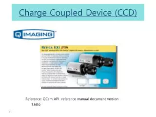
Specifications • Features • High quantum Efficiency • 1.4 Million pixel, 1360×1036 • 110 fps 8×8 binning mode, 10fps @ full resolution • External sync and trigger • Peltier cooling • Binning 2×2, 4×4, 8×8 • IEEE Fast1394 • Digital output: 12Bit • Exposure control 40μs~17.9 min • Gain control • Offset control • Powered from IEEE1394 cable, 11watts(Cooled), 6watts(Uncooled)
Micro beads observation through CCD Bright field imaging 4.45um bead Fluorescence imaging
CCD API PC qcamera.h qcamdriver.lib API IEEE 1394 Interface CCD
Function List, type and Flow chart • Functions • QCam_ListCameras(); • QCam_OpenCamera(); • QCam_CloseCamera(); • QCam_LoadDriver(); • QCam_ReleaseDriver(); • QCam_BayerToRgb(); • QCam_CalcImageSize(); • QCam_GrabFrame(); • QCam_ReadDefaultSettings(); • QCam_SendSettingsToCam(); • QCam_SetParam(); • Types • QCam_CamListItem • QCam_Err • QCam_Frame • QCam_Handle • QCam_ImageFormat • QCam_Settings QCam_LoadDriver() QCam_OpenCamera() QCam_GrabFrame() N Acquisition Complete? Y QCam_CloseCamera() QCam_ReleaseDriver()
High Speed CMOS Camera MikrotronEoSens CL MC-1362
Specifications • Features • Monochrome • Maximum Photo Sensitivity (2500 ASA Monochrome, 700 ASA RGB) • 1280(H) x 1024(V) CMOS-Sensor • Pixel size : 14x14um • Active area: 17.92mm x 14.34mm • Spectral response: 400~720nm • Up to 500 Frames per Second (fps) at Full Resolution • Up to 120,000 fps at Reduced Resolution • Base or Full Camera Link® Interface with 700/160 MB/Second • Serial data link: RS-644 in base camera link, 9.6-115KBd, 8bits • Extended Dynamic Range up to 90 dB • Multiple Frame Exposure • Multiple RoI • X- and Y-Mirroring of Image Data • Small and Compact Design • Optional C-/F-Mount Lens Mount
How to interface with a computer? PC API NI IMAQ Vision Library niimaq.h imaq.lib Full link (High speed image acquisition) Base link (Camera control) CMOS Camera NI PCIe-1429 Digital Frame Grabber
Frame grabber (NI PCIe-1429) • Frame grabber is used to acquire images at highest speeds, resolutions, • and bit depths available for the CMOS camera. • Features • Image acquisition for base, medium, and full-configuration Camera Link cameras • Four-lane (x4) PCI Express interface • Standard Camera Link cabling • Data format: 24 bits • Maximum camera link rate: base(340 MB/s), full(680 MB/s) • Optional digital I/O expansion card for extra triggering and isolation • Driver Software (included): NI-IMAQ 3.1
NI Imaq Vision Library • Interface functions To set up and close the interface and session Ex) imgInterfaceOpen, imgSessionOpen, imgClose • Acquisition Functions To configure, start, and abort an image acquisition. Ex) imgSessionStartAcquisition, imgSessionStopAcquisition, imgRingSetup • Utility functions To display an image in a window, save an image to a file, or get detailed error information. Ex) imgPlot, imgSessionSaveBufferEx • Serial Communication Functions For devices that support serial communication Ex) imgSessionSerialWrite, imgSessionSerialRead, imgSessionSerialFlush
Example code imgInterfaceOpen() imgSessionOpen() imgRingSetup() imgSessionStartAcquisition() imgSessionExamineBuffer2() N Acquisition Complete? Y imgSessionStopAcquisition() imgClose()
Example code (cont’d) All acquired frames are saved in the format of “*.jpg files” 1.jpg


![[Reference]](https://cdn3.slideserve.com/6885011/reference-dt.jpg)
![[Reference]](https://cdn3.slideserve.com/6885026/reference-dt.jpg)