Review of Bump Closure and Chicane Powering for PSB 160 MeV H- Injection Efficiency
110 likes | 228 Vues
This review analyzes the influence of chicane magnets and dipole configurations on bump closure during the PSB 160 MeV H- injection process. It discusses the modeling of various multi-turn variants and their feasibility, alongside the impact of main dipoles on the overall system performance. Key aspects include simulation results showcasing the accuracy of bump closure, tolerance requirements, and multiple powering solutions for the chicane magnets. The findings contribute valuable insights for optimization and implementation strategies for future upgrading of the injection system.

Review of Bump Closure and Chicane Powering for PSB 160 MeV H- Injection Efficiency
E N D
Presentation Transcript
BI.BSW Chicane Magnets review D. Aguglia, B. Balhan, J. Borburgh, C. Bracco, B. Goddard, D. Nisbet
Contents Bump closure Influence from the main dipoles Multi turn (>2) variants feasibility Chicane powering Review follow up on PSB 160 MeV H- injection
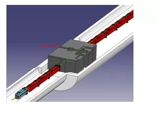
Bump closure simulation 1/3 (action 6,7,8) • 4 BSW’s (1 ring) modelled in single FE model (Vector Fields). • No cross talk between magnets observed. • Bump closure simulated at nominal current: bump is closed within the accuracy of the model (mesh size ~2mm). Complete field map available. Review follow up on PSB 160 MeV H- injection
Bump closure simulation 2/3 Not to scale Review follow up on PSB 160 MeV H- injection
Bumpclosure 3/3required/assumedtolerances • The non-closure amplitude is estimated assuming 66 mrad deflection and 6 m average H beta function, with uncorrelated errors • *Note that for the vertical orbit non-closure, the roll angle tolerance of the dipole magnets is about 1 mrad (much more sensitive) • Tolerances are typically 1e-3, and 1 mrad alignment, except yaw which can be 20-30 mrad • Tracking accuracy of individual supplies will need to be better than 1e-3 Review follow up on PSB 160 MeV H- injection
Influence of the main dipoles (action 8, 22) • A very large model with a ¼ of BHZ and BS1(ring 3 and 4) was created in Vector Fields. • Field has been analysed to study effect on BS1 at injection (160 MeV). • Model was made available to the MSC group to assess the impact of the BSW’s on the BHZ. Review follow up on PSB 160 MeV H- injection
Influence of BHZ on BS1 at injection Small reduction of ∫B.dl of BSW (~3‰) Very limited effect on field homogeneity Effect on BS4 still to be quantified Complete field map available Review follow up on PSB 160 MeV H- injection
Multi-turn BSW variants (action 9) • 8 turn version feasible for window frame variants (BSW2,3,and4). • Only 2 or possibly 4 turn variant possible for septum (BSW1). Depending on leak field requirements (still to be defined and calculated). Review follow up on PSB 160 MeV H- injection
Chicane powering (action 5) 1/3 2 different nominal currents (BSW1 and BSW2-4), with separate power supplies for each. Current setting individually adjustable for each magnet (±5% w.r.t nominal setting). Transformers in tunnel from BSW1’s (4 in total) in case 2 turn magnets. Transformers might be put farther from injection area in case of 4 turn magnets. No transformers needed in tunnel for 8-turn BSW’s. Review follow up on PSB 160 MeV H- injection
Chicane powering (action 5) 2/3 • Powering solution 1 • BSW1 at 13.5kA individual (4x), BSW2,3&4 3.4 kA individual (12x). • Powering solution 2 • BSW1 at 13.5kA individual (4x), BSW2&3 3.4 kA in series (4x), BSW4 3.4 kA individual (4x). • Powering solution 3 • BSW1 power supplies 13.5 kA (4 x), BSW2-4 power supplies 3.4 kA (4 x), Trim power supplies for BSW4 and BSW3 (200A, 8 x). Review follow up on PSB 160 MeV H- injection
Chicane powering (action 5) 3/3 Solution 1 Solution 2 Solution 3 • Powering solution 1: full optics control, Power conv. low development risk, the most voluminous. • Powering solution 2: reduced optics control, Power conv. low development risk, less voluminous w.r.t. solution 1. • Powering solution 3: full optics control, Power conv. increased development risk, least voluminous solution, more complex controls, NEEDS MORE DEVELOPMENT EFFORTS. Possible circuit diagrams Review follow up on PSB 160 MeV H- injection