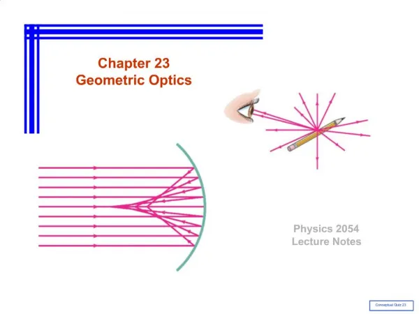
Chapter 17 Optics
Chapter 17 Optics. 17.1 Reflection and Refraction 17.2 Mirrors, Lenses, and Images 17.3 Optical Systems. Chapter 17 Objectives. Describe the functions of convex and concave lenses, a prism, and a flat mirror. Describe how light rays form an image.

Chapter 17 Optics
E N D
Presentation Transcript
Chapter 17 Optics 17.1 Reflection and Refraction 17.2 Mirrors, Lenses, and Images 17.3 Optical Systems
Chapter 17 Objectives Describe the functions of convex and concave lenses, a prism, and a flat mirror. Describe how light rays form an image. Calculate the angles of reflection and refraction for a single light ray. Draw the ray diagram for a lens and a mirror showing the object and image. Explain how a fiber-optic circuit acts like a pipe for light. Describe the difference between a real image and a virtual image and give an example of each.
Chapter 17 Vocabulary Terms • angle of refraction • chromatic • aberration • converging lens • critical angle • diffuse reflection • dispersion • diverging lens • eyepiece • fiber optics • focal length • focal plane • focal point • focus • geometric optics • image • image relay • incident ray • index of refraction • law of reflection • lens • magnification • magnifying glass • mirror • normal line • object • objective • optical axis • optics • prism • ray diagram • real image • reflected ray • refracting telescope • Snell’s law • specular reflection • spherical aberration • telescope • thin lens formula • total • internal reflection • virtual
Inv 17.1 Reflection and Refraction Investigation Key Question: How do we describe the reflection and refraction of light?
17.1 Reflection and Refraction The overall study of how light behaves is calledoptics. • The branch of optics that focuses on the creation of images is called geometric optics, because it is based on relationships between angles and lines that describe light rays.
17.1 Reflection and Refraction A lens is an optical device that is used to bend light in a specific way. A converging lens bends light so that the light rays come together to a point. A diverging lens bends light so it spreads light apart instead of coming together.
17.1 Reflection and Refraction Mirrors reflect light and allow us to see ourselves. A prism is another optical device that can cause light to change directions. A prism is a solid piece of glass with flat polished surfaces.
17.1 Reflection Images appear in mirrors because of how light is reflected by mirrors. Theincident ray follows the light falling onto the mirror. The reflected ray follows the light bouncing off the mirror.
17.1 Reflection In specular reflection each incident ray bounces off in a single direction. A surface that is not shiny creates diffuse reflection. In diffuse reflection, a single ray of light scatters into many directions.
Law of Reflection The incident ray strikes the mirror. The reflected ray bounces off. The angle of incidence equals the angle of reflection.
Law of reflection A light ray is incident on a plane mirror with a 30 degree angle of incidence. Sketch the incident and reflected rays and determine the angle of reflection. • You are given the angle of incidence. • Use the law of reflection which states the angle of reflection equals the angle of incidence. • Sketch a ray diagram showing the angle of reflection is 30o. • You are asked for a ray diagram and the angle of reflection.
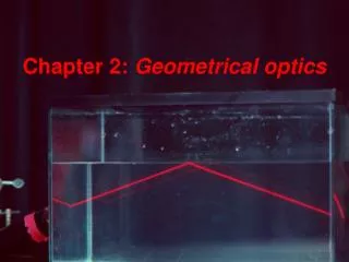
17.1 Refraction Light rays may bend as they cross a boundary from one material to another, like from air to water. This bending of light rays is known as refraction. The light rays from the straw are refracted (or bent) when they cross from water back into air before reaching your eyes.
17.1 Refraction When a ray of light crosses from one material to another, the amount it bends depends on the difference in index of refraction between the two materials.
17.1 Index of refraction The ability of a material to bend rays of light is described by the index of refraction (n).
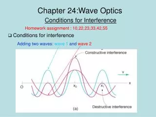
17.1 Snell's law of refraction Snell’s law is the relationship between the angles of incidence and refraction and the index of refraction of both materials. Angle of refraction (degrees) Angle of incidence (degrees) ni sini= nr sin r Index of refraction of incident material Index of refraction of refractive material
17.1 Relection and the critical angle • The angle of incidence at which light begins reflecting back into a refractive material is called the critical angle. • The critical angle depends on the index of refraction.
Calculating the angle of refraction • You are asked for the angle of refraction. • You are given the angle of incidence, and materials. • Use Snell’s law: ni sin i = nr sin r • Solve sin r = 1.00 sin (30o) ÷ 1.33 sin r = 0.376 r = sin-1 (0.376) = 22o A ray of light traveling through air is incident on a smooth surface of water at an angle of 30° to the normal. Calculate the angle of refraction for the ray as it enters the water.
17.1 Dispersion and prisms When white light passes through a glass prism, blue is bent more than red. Colors between blue and red are bent proportional to their position in the spectrum.
17.1 Dispersion and prisms The variation in refractive index with color is called dispersion. A rainbow is an example of dispersion in nature. Tiny rain droplets act as prisms separating the colors in the white light rays from the sun.
Chapter 17 Optics 17.1 Reflection and Refraction 17.2 Mirrors, Lenses, and Images 17.3 Optical Systems
Inv 17.2 Mirrors, Lenses, and Images Investigation Key Question: How does a lens or mirror form an image?
17.2 Mirrors, Lenses, and Images We see a world of images created on the retina of the eye by the lens in the front of the eye.
17.2 Mirrors, Lenses, and Images Objects are real physical things that give off or reflect light rays. Images are “pictures” of objects that are formed in space where light rays meet.
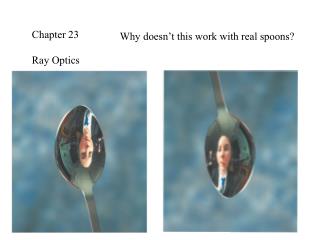
17.2 Mirrors, Lenses, and Images The most common image we see every day is our own reflection in a mirror. The image in a mirror is called a virtual image because the light rays do not actually come together. • The virtual image in a flat mirror is created by the eye and brain.
17.2 Mirrors, Lenses, and Images Light rays that enter a converging lens parallel to its axis bend to meet at a point called the focal point. The distance from the center of the lens to the focal point is called the focal length. The optical axis usually goes through the center of the lens.
17.2 The image formed by a lens A lens can form a virtual image just as a mirror does. Rays from the same point on an object are bent by the lens so that they appear to come from a much larger object.
17.2 The image formed by a lens A converging lens can also form a real image. In a real image, light rays from the object actuallycome back together.
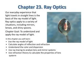
17.2 Drawing ray diagrams A ray diagram is the best way to understand what type of image is formed by a lens, and whether the image is magnified or inverted. These three rays follow the rules for how light rays are bent by the lens: A light ray passing through the center of the lens is not deflected at all (A). A light ray parallel to the axis passes through the far focal point (B). A light ray passing through the near focal point emerges parallel to the axis (C).
17.2 Characteristics of images • A real image is formed by the actual intersection of light rays from the object. • Real images can be projected on a surface.
17.2 Characteristics of images • A converging lens acts as a magnifying glass when the object is closer to the lens than one focal length.
17.2 Characteristics of images • A diverging lens is thicker around the edges and thinner in the center. • The image formed by a diverging lens is virtual and right side up.
17.2 Characteristics of images • The magnification varies for single lenses- it depends on the distance of the object from the lens.
Chapter 17 Optics 17.1 Reflection and Refraction 17.2 Mirrors, Lenses, and Images 17.3 Optical Systems
Inv 17.3 Optical Systems Investigation Key Question: How are the properties of images determine?
An optical system is a collection of mirrors, lenses, prisms, or other optical elements that performs a useful function with light. Characteristics of optical systems are: The location, type, and magnification of the image. The amount of light that is collected. The accuracy of the image in terms of sharpness, color, and distortion. The ability to change the image, like a telephoto lens on a camera. The ability to record the image on film or electronically. 17.3 Optical Systems
17.3 The sharpness of an image Defects in the image are called aberrationsand can come from several sources. • Chromatic aberration is caused by dispersion, when different colors focus at different distances from the lens.
17.3 The sharpness of an image • Spherical aberration causes a blurry image because light rays farther from the axis focus to a different point than rays near the axis.
17.3 Thin lens formula The thin lens formula is a mathematical way to do ray diagrams with algebra instead of drawing lines on graph paper. 1 + 1 = 1 do di df Object distance (cm) focal length (cm) Image distance (cm)
Locating an image • You are asked for the image distance. • You are given focal length and object distance. • Use thin lens formula 1 + 1 = 1 do di df • Solve for 1=1-1 = 3- 2= 1di = 12 cm di 4 6 12 12 12 Calculate the location of the image if the object is 6 cm in front of a converging lens with a focal length of 4 cm.
17.3 Changing the size of an image A technique known as image relay is used to analyze an optical system made of two or more lenses.
17.3 Recording images • There are two basic techniques for recording images. • Film records an image by using special inks that respond to light. • A digital camera uses a tiny sensor called a CCD.
17.3 Recording images • There are separate light sensors for red light, blue light, and green light. • A color image is recorded as a table of numbers. • Each point on the image has three numbers corresponding to the amount of red light, blue light, and green light.
17.3 Recording images • The resolution of a digital camera is the number of points, called pixels, that can be recorded by the CCD. • A 2-megapixel camera stores 2 million pixels per image. • Since each pixel is three numbers, a 2-megapixel image requires 6 million stored numbers.
17.3 The Telescope • When people think of a telescope, most of them think of a refracting telescope. • An astronomical refracting telescope is constructed of two converging lenses with different focal lengths. • The lens with the longest focal length is called the objective and the shorter-focal-length lens is the eyepiece.
17.3 The Telescope • The image from this refracting telescope is inverted which is usually fine for looking at objects in space.
17.3 The Telescope • The design of the terrestrial telescope sets the lenses a distance apart equal to the sum of their focal lengths. • This design aids viewing animals or birds right side up.
Newtonian Reflecting Telescope • The most successful reflecting-telescope design is called a Newtonian telescope, after Sir Isaac Newton, who designed and built the first one. • The larger the diameter of the objective of a telescope, the more light it can gather to form an image. • The Hubble telescope is unique because it orbits well above Earth’s atmosphere so there is no distortion from atmospheric refraction.