Chapter 24:Wave Optics
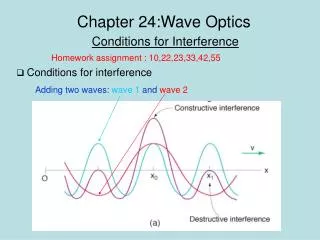
Chapter 24:Wave Optics. Homework assignment : 10,22,23,33,42,55 . Conditions for interference. Adding two waves: wave 1 and wave 2. Conditions for Interference. Conditions for Interference. Conditions for interference (cont’d).

Chapter 24:Wave Optics
E N D
Presentation Transcript
Chapter 24:Wave Optics Homework assignment : 10,22,23,33,42,55 • Conditions for interference Adding two waves: wave 1 and wave 2 Conditions for Interference
Conditions for Interference • Conditions for interference (cont’d) • Two sources producing two traveling waves are needed to create • interference. • The sources must be coherent, which means the waves they emit • must maintain a constant phase with respect to each other. • The waves must have identical wavelengths. An old style method to produce two coherent sources
Conditions for Interference • Two slits and interference Two monochromatic sources of the same frequency and with any Constant phase relation are said to be coherent.
Young’s Double-Slit Experiment • Young’s double-slit experiment • Red dots represent spots • where the two waves are • in phase and constructive • interference occurs. This • produces bright spots. • Blue circles represent spots • where the two waves are • out of phase and destructive • interference occurs. This • produces dark spots.
Young’s Double-Slit Experiment • Young’s double-slit experiment (cont’d) In phase Out of phase In phase Bright image Dark image Bright image
Young’s Double-Slit Experiment • Young’s double-slit experiment (cont’d) Path difference : Constructive interference: m : order number m=0 zeroth-order, m=+-1 first-order… Destructive interference :
Young’s Double-Slit Experiment • Young’s double-slit experiment (cont’d) Constructive interference: Destructive interference:
Young’s Double-Slit Experiment • Example 24.1: Measuring the wavelength of a light source • A screen is separated from a double-slit source by 1.20 m. The • distance between the two slits is 0.0300 mm. The second-order • bright fringe (m=2) is measured to be 4.50 cm from the centerline. • Determine: • (a) the wavelength of the light • (b) the distance between the adjacent bright fringes.
Change of Phase Due to Reflection • Lloyd’s mirror • In the arrangement of a mirror • and the screen on the right, at • a point on the screen the light • waves have two possible paths. • At point P’, the path difference • of two paths is zero: Therefore • we expect a bright fringe. But we • see a dark fringe there. • Similarly on the screen the pattern • of bright and dark fringes is reversed. An EM wave undergoes a phase change of 180o or p upon reflection from a medium that has an index of refraction higher than the one in which the wave is traveling.
Change of Phase Due to Reflection • Phase change upon reflection An EM wave undergoes a phase change of 180o upon reflection from a medium that has an index of refraction higher than the one in which the wave is traveling.
Interference in Thin Film • Colorful patterns
Interference in Thin Film • Interference in thin film • An EM wave traveling from a medium of index of refraction n1 • toward a medium of index of refraction n2 undergoes a p • phase change on reflection when n2>n1. • There is no phase change in the reflected light wave if n1>n2. • The wavelength of light ln in a medium with index of refraction n is • ln=l/n where l is the wavelength of light in vacuum. Ray 1: A phase change of p at surface A with respect to the incident wave (n>nair=1) phase diff. by p due to reflection Ray 2: No phase change at surface B with respect to the incident wave (n>nair=1) Phase difference Ray 1 : p Ray 2 : 2p x 2t/ln constructive destructive
Interference in Thin Film • Interference in thin film (cont’d) Interference between ray 1 and ray 2 constructive destructive thicker due to gravity
Interference in Thin Film • Newton’s Rings • Another example of interference: • A planoconvex lens on top of a flat glass • surface Blue ray : phase change at the interface between air and a flat glass. phase diff. by p due to reflection Red ray : no phase change due to reflection. Interference between red and blue ray constructive destructive
Interference in Thin Film • Non-reflective coating for optical lens Air, n = 1.00 MgF2 n = 1.38 t Glass, n = 1.50 Thin layer of MgF2 with index intermediate between air and glass; there are two phase shifts of in this case, as shown. Phase shifts of reflected rays: Ray 1: Ray 2: + (2p/ln)(2t) For no reflection: (2p/ln) (2t) = (destructive interference) Numbers: for no reflection at = 550 nm, t = 100 nm.
Interference in Thin Film • Interference in a wedge-shaped film A pair of glass slides 10.0 cm long and with n=1.52 are separated on one end by a hair, forming a triangular wedge of air as illustrated. When coherent light from a helium-neon laser with wavelength 633 nm is incident on the film from above, 15.0 dark fringes per cm are observed. How thick is the hair? For destructive interference with nair=1: If d is the distance from one dark band to the next, the x-coord. of the m-th fringe is: Using similar triangles :
Diffraction • What is diffraction? Diffraction is bending of waves around obstacles. Diffraction also occurs when waves from a large number of sources interfere.
Diffraction • Single slit Bending on the corner
Single slit Diffraction at slits
Diffraction at slits • Diffraction and Huygens principle Every point on a wave front acts as a source of tiny wavelets that move forward. • Light waves originating at different points within opening travel different distances to wall, and can interfere! • We will see maxima and minima on the wall.
Single slit 1 1 1 1 a a = path difference = path difference Diffraction at slits When a/4 sin q = l/2 every ray originating in top quarter of slit interferes destructively with the corresponding ray originating in the second quarter. Whena/2 sin q = l/2 every ray originating in top half of slit interferes destructively with the corresponding ray originating in bottom half.
Single slit Condition for halves of slit to destructively interfere Condition for quarters of slit to destructively interfere Condition for sixths of slit to destructively interfere All together… Diffraction at slits This formula locates minima (for dark fringes)!!
Diffraction grating • Combination of diffraction and • interference • Consists of a large number of • equally spaced parallel slits. • Can be made by scratching • parallel lines on a glass plate • with a precision machine • technique. Diffraction Grating • Each slit causes diffraction. • Each slit acts as a source of waves in phase. • Path diff. between two adjacent slits at P: • If slits are made to satisfy : waves from slits are in phase. d=spacing of slits qbright are the positions of bright maxima.
Diffraction grating (cont’d) Diffraction Grating Pattern of light intensity Diffraction grating spectrometer By measuring the positions of maxima, using the telescope in a diffraction grating spectrometer, the wavelength of the incident waves can be determined.
EM wave vector in x-dir. vector in y-dir. • Polarization (defined by the direction of ) Polarization Linear polarization Circular polarization If the E-field is in the same direction all the time, the EM wave is linearly polerized.
Polarization (defined by the direction of ) Circular polarization Polarization (cont’d)
Polarization by reflection Polarization (cont’d) plane of incidence When the angle of incident coincides with the polarizing angle or Brewster’s angle, the reflected light is 100% polarized. Brewsters’ law of the polarizing angle
Polarization by absorption and polarizing filters Polarization (cont’d) Polaroid: polarizes light through selective absorption by oriented molecules These molecules have a preferred axis (transmission axis) along which electrons can move easily. All lights with E parallel (perpendicular) to the axis is transmitted (absorbed).
Malus’s Law • Malus’s law • When linearly polarized light passes through a polarizer whose axis of transmission make an angle q with the direction of the E-field vector (or polarization), the intensity of the light follows the law: • Unpolarized light (like the light from the sun) passes through a polarizing sunglass (a linear polarizer). The intensity of the light when it emerges is:
Malus’s law (cont’d) Malus’ law for polarized light passing through an analyzer/polarizer: Malus’s Law This is true only when the incident light is linearly polarized.
Malus’s Law Unpolarized light on linear polarizer • Most light comes from electrons accelerating in random directions and is unpolarized. • Averaging over all directions, intensity of transmitted light reduces due to reduction in E
Malus’s Law Example:Malus’s law I1 I = I0 I3 • Intensity of unpolarized light incident on linear polarizer is reduced by half . I1= I0 / 2 • Now ignore the 2nd polarizer for now. 3) Light transmitted through first polarizer is vertically polarized. Angle between it and 3rd polarizer is q=90º . I3= I1 cos2(90º) = 0
Malus’s Law Example: Malus’s law I1= 0.5 I0 I1 I2= I1cos2(45) I2 1) Now put 2nd polarizer in. 2) Light transmitted through first polarizer is vertically polarized. Angle between it and second polarizer is q=45º. I2= I1 cos2 (45º)=0.5I1=0.25 I0 3) Light transmitted through second polarizer is polarized 45º from vertical. Angle between it and third polarizer is q=45º. I3= I2 cos2(45º) =0.125 I0
Malus’s Law Example: Malus’s law
Controlled Polarization • LCD screen • Electrical voltage on a liquid crystal diode • Turns on and off polarizing filter effect • Used in LCD display