Download
1 / 97
1.1k likes | 1.86k Vues
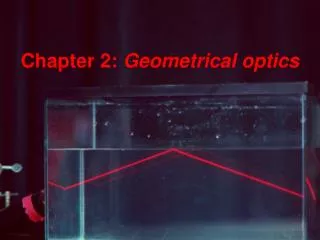
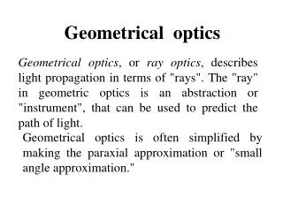
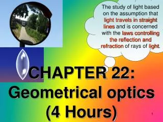
The study of light based on the assumption that light travels in straight lines and is concerned with the laws controlling the reflection and refraction of rays of light. CHAPTER 22: Geometrical optics (4 Hours). UNIT 22 : GEOMETRICAL OPTICS. 22.1 Reflection at a spherical surface

E N D
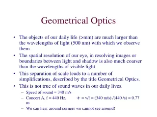
The study of light based on the assumption that light travels in straight lines and is concerned with the laws controlling the reflection and refraction of rays of light. CHAPTER 22: Geometrical optics(4 Hours)
UNIT 22 : GEOMETRICAL OPTICS 22.1 Reflection at a spherical surface 22.2 Refraction at a plane and spherical surfaces 22.3 Thin lenses
At the end of this topic, students should be able to: ( 1 H) 22.1 Reflection at a spherical surface a) State laws of reflection. b) Sketch and use ray diagrams to determine the characteristics of image formed by spherical mirrors. c) Use For real object only • Usesign convention for focal length: + f for concave mirror and – ffor convex mirror. • Sketchray diagrams with minimum two rays. • r = 2f only applies to spherical mirror.
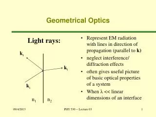
The Law of reflection The law of reflection states that • The incident ray, the reflected ray and normal, all lie in the same plane • The angle of incidence i is equal to the angle of reflection r.
22.1 Reflection at a spherical surface Terms and Definitions • A spherical mirror is a reflecting surface • with spherical geometry. • Two types : • i) convex, if the reflection takes place on • the outer surfaceof the spherical shape. • ii) concave, if the reflecting surface is on • the inner surfaceof the sphere.
22.1 Reflection at a spherical surface Terms and Definitions Imaginary spherical A A P C P C F F B B f f r r A concave mirror A convex mirror C ~ centre of curvature of the surface mirror. P ~ centre of the surface mirror (vertex or pole). Line CP ~ principal or optical axis.
22.1 Reflection at a spherical surface Imaginary spherical Terms and Definitions A A P C P C F F B B f f r r AB ~ aperture of the mirror. F ~ focal point of the mirror. f ~ focal length (FP, distance between focal point and the centre of the mirror). r ~ radius of curvature of the mirror.
C C P P F F Focal point and focal length, f Incident rays Incident rays • Consider the ray diagram for a concave and convex mirrors as shown in Figures 1.8a and 1.8b. • Point F represents the focal point or focus of the mirrors. • Distance f represents the focal length of the mirrors. • The parallel incident rays represent the object infinitely far away from the spherical mirror e.g. the sun. Figure 1.8a Figure 1.8b
Focal point or focus, F • For concave mirror – is defined as a point where the incident parallel rays converge after reflection on the mirror. • Its focal point is real (principal). • For convex mirror – is defined as a point where the incident parallel rays seem to diverge from a point behind the mirror after reflection. • Its focal point is virtual. Focal length, f • is defined as the distance between the focal point (focus) F and pole P of the spherical mirror. • The paraxial rays is defined as the rays that are near to and almost parallel to the principal axis.
A M P C F f r 22.1 Reflection at a spherical surface Relation between focal length, f and radius of curvature, r is isosceles. (FC=FM) Consider ray AM is paraxial (parallel and very close to the principal axis). FM = FP or FP = 1/2 CP
Ray diagrams for spherical mirrors • is defined as the simple graphical method to indicate the positions of the object and image in a system of mirrors or lenses. Images formed by a concave mirror • Ray diagram Ray 1 : A ray parallel to the principal axis is reflected through the focus (focal point).
Ray diagram Ray 2 : A ray passing through the focus is reflected parallel to the principal axis. Ray 3 :A ray passing through the centre of curvature is reflected back through the centre of curvature.
Images formed by a concave mirror • Concave mirror can be used as a shaving and makeup mirrors because it provides an upright and virtual images. • Table 1.1 shows the ray diagrams of locating an image formed by a concave mirror for various object distance, u. * Remember: At least any two rays for drawing the ray diagram
C P F Front back F P C Front back • Real • Inverted • Diminished • Formed between point C and F. u > r • Real • Inverted • Same size • Formed at point C. u = r
C P F Front back P F C Front back • Real • Inverted • Magnified • Formed at a distance greater than CP. f < u < r • Real or virtual • Formed at infinity. u = f
F P C Front back • Virtual • Upright • Magnified • Formed at the back of the mirror u < f Table 1.1
F Notes Image formed by concave mirrors • If the object is at infinity, a real image is • formed at F. Conversely, an object at F • gives a real image at infinity. 5) Object at infinity • At F • Real • Inverted • Smaller than object ii) In all cases, the foot of the object is on the principal axis and its image also lies on this line.
Image formed by a convex mirror Ray 1 :A ray parallel to the axis is reflected as though it came from the focal point. Ray 2 :A ray heading toward the focal point is reflected parallel to the axis. Ray 3 :A ray heading toward the centre of curvature is reflected back on itself.
Image formed by a convex mirror • The characteristics of the image formed are • virtual • upright • diminished (smaller than the object) • formed at the back of the mirror (behind the mirror) • Object position any position in front of the convex mirror. • Convex mirror always being used as a driving mirror because it has a wide field of view and providing an upright image.
b) The mirror equation-calculation using formula A P B M v r u
b) The mirror equation-calculation using formula Object distance = OP = u Image distance = IP = v Radius of curvature = CP = r Object size = OA = h Image size = IB = h’ Focal length = f or
Linear Magnification, m • Linear (lateral) magnification of the spherical mirror, m is defined as the ratio between image height, hi and object height, ho where
Table 1.2 shows the sign convention for spherical mirror’s equation . • Note: • Real image is formed by the actual light rays that pass through the image. • Real image can be projected on the screen. Virtual object Real object Object distance, u (in front of the mirror) (at the back of the mirror) Real image Virtual image Image distance, v (same side of the object) (opposite side of the object) Focal length, f Concave mirror Convex mirror Table 1.2
Example 22.1.1 : A dentist uses a small mirror attached to a thin rod to examine one of your teeth. When the tooth is 1.20 cm in front of the mirror, the image it forms is 9.25 cm behind the mirror. Determine a. the focal length of the mirror and state the type of the mirror used, b. the magnification of the image. Solution :
Example 22.1.2: An upright image is formed 20.5 cm from the real object by using the spherical mirror. The image’s height is one fourth of object’s height. a. Where should the mirror be placed relative to the object? b. Calculate the radius of curvature of the mirror and describe the type of mirror required. c. Sketch and label a ray diagram to show the formation of the image. Solution :
Example 22.1.3 : A person of 1.60 m height stands 0.60 m from a surface of a hanging shiny globe in a garden. a. If the diameter of the globe is 18 cm, where is the image of the person relative to the surface of the globe? b. How large is the person’s image? c. State the characteristics of the person’s image. Solution :
Example 22.1.4 : A shaving or makeup mirror forms an image of a light bulb on a wall of a bathroom that is 3.50 m from the mirror. The height of the bulb is 8.0 mm and the height of its image is 40 cm. a. Sketch a labeled ray diagram to show the formation of the bulb’s image. b. Calculate i. the position of the bulb from the pole of the mirror, ii. the focal length of the mirror. Solution :
Exercise: 1. a. A concave mirror forms an inverted image four times larger than the object. Calculate the focal length of the mirror, assuming the distance between object and image is 0.600 m. b. A convex mirror forms a virtual image half the size of the object. Assuming the distance between image and object is 20.0 cm, determine the radius of curvature of the mirror. ANS. : 160 mm ; 267 mm 2. a. A 1.74 m tall shopper in a department store is 5.19 m from a security mirror. The shopper notices that his image in the mirror appears to be only 16.3 cm tall. i. Is the shopper’s image upright or inverted? Explain. ii. Determine the radius of curvature of the mirror. b. A concave mirror of a focal length 36 cm produces an image whose distance from the mirror is one third of the object distance. Calculate the object and image distances. ANS. : u think, 1.07 m ; 144 cm, 48 cm
3. If a concave mirror has a focal length of 10 cm, find the two positions where an object can be placed to give, in each case, an image twice the height of the object.( 15cm, 5.0cm ) • 4. A convex mirror of radius of curvature 40 cm forms an image which is half the height of the object. Find the object and image position.( 20cm,10cm behind the mirror )
5. What are the nature, size, and location of the image formed when a 6 cm tall object is located 15 cm from a spherical concave mirror of focal length 20 cm ? (virtual, upright, -60 cm, + 24 cm)
22.2 Refraction at a plane and spherical surfaces (1 H) At the end of this chapter, students should be able to: • State and usethe laws of refraction (Snell’s Law) for layers of materials with different densities. • Apply for spherical surface.
22.2 Refraction at a plane and spherical surfaces 22.2.1 Refraction at a plane surface • Refraction is defined as the changing of direction of a light ray and its speed of propagation as it passes from one medium into another. • Laws of refraction state : • The incident ray, the refracted ray and the normal all lie in the same plane. • For two given media, Snell’s law states OR where
Incident ray Incident ray Refracted ray Refracted ray (a) (b) (Medium 1 is less dense medium 2) (Medium 1 is denser than medium 2) • Examples for refraction of light ray travels from one medium to another medium can be shown in Figures 1.13a and 1.13b. Figure 1.13a Figure 1.13b The light ray is bent away from the normal, thus The light ray is bent toward the normal, thus
Refractive index (index of refraction), n • is defined as the constant ratio for the two given media. • The value of refractive index depends on the type of medium and the colour of the light. • It is dimensionless and its value greater than 1. • Consider the light ray travels from medium 1 into medium 2, the refractive index can be denoted by (Medium containing the refracted ray) (Medium containing the incident ray)
Absolute refractive index, n (for the incident ray travels from vacuum or air into the medium) is given by • Table 1.3 shows the refractive indices for common substances. Table 1.3 2.42 1.66 1.52 1.46 1.31 Solids Diamond Flint glass Crown glass Fused quartz (glass) Ice (If the density of medium is greater hence the refractive index is also greater) Liquids Benzene Ethyl alcohol Water 1.50 1.36 1.33 Gases Carbon dioxide Air 1.00045 1.000293
Relationship between refractive index and the wavelength of light • As light travels from one medium to another, its wavelength, changes but its frequency, f remains constant. • The wavelength changes because of different material. The frequency remains constant because the number of wave cycles arriving per unit time must equal the number leaving per unit time so that the boundary surface cannot create or destroy waves. • By considering a light travels from medium 1 (n1) into medium 2 (n2), the velocity of light in each medium is given by then and where and
If medium 1 is vacuum or air, then n1 = 1. Therefore the refractive index for any medium, n can be expressedas (Refractive index is inversely proportional to the wavelength) where
Example 22.2.1 : A fifty cent coin is at the bottom of a swimming pool of depth 3.00 m. The refractive index of air and water are 1.00 and 1.33 respectively. Determine the apparent depth of the coin. Solution :
Example 22.2.2 : A pond with a total depth (ice + water) of 4.00 m is covered by a transparent layer of ice of thickness 0.32 m. Determine the time required for light to travel vertically from the surface of the ice to the bottom of the pond. The refractive index of ice and water are 1.31 and 1.33 respectively. (Given the speed of light in vacuum is 3.00 108 m s-1.) Solution :
22.2.2 Refraction at a spherical surface • Figure 1.14 shows a spherical surface with radius, r forms an interface between two media with refractive indices n1 and n2. • The surface forms an image I of a point object O. • The incident ray OB making an angle i with the normal and is refracted to ray BI making an angle where n1 < n2. • Point C is the centre of curvature of the spherical surface and BC is normal. Figure 1.14
(1) (2) (3) • From the figure, BOC BIC • From the Snell’s law By using BOD, BCD and BID thus By considering point B very close to the pole P, hence then Snell’s law can be written as