Download
1 / 34
340 likes | 363 Vues
Learn how to optimize energy usage in embedded systems using efficient switching power supplies and real-time scheduling techniques. Explore challenges, solutions, and evaluation methods in noise reduction and energy optimization.

E N D
Reducing Noise and System Costs by Managing Switching Power Supplies as Real-Time Processes Subash Sachidananda & Dr. Alex Dean Dept. of ECE - NC State University
EMI- and Energy-Aware Scheduling of Switching Power Supplies in Hard Real-Time Embedded Systems Subash Sachidananda & Dr. Alex Dean Dept. of ECE - NC State University RTAS 2011
Overview Real-Time Systems • Goal • Switch mode power supplies (SMPS) • Real-time scheduling • Our work Energy Optimization Embedded Systems Energy Optimization Switching Power Supplies
Goal • Reduce power and energy used by embedded computing systems in a cost-effective way • Basics • Two parts: Static and dynamic • P = SPVCC2 + CPVCC2fClock • Power aV2 • Energy is power * time • Competing pressures for energy optimization • Shut off unused subsystems • When running, run as fast as possible to minimize static power (must raise supply voltage to speed up clock) • When running, use minimum voltage which supports logic’s clock frequency
Switching Power Converters • Function • Efficient conversion of voltage up (boost) or down (buck), or both (buck-boost) • Benefits • Can run circuitry at lowest feasible voltage • Can scale voltage dynamically as needed to support changing clock speed • Battery voltage variations across discharge curve do not affect operating point of circuit
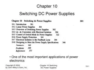
Boost Converter Operation • Switch (transistor) S turns on • Current starts flowing through inductor L and S • Switch S turns off • Current flowing through L now goes through diode to charge C and power load
Switching Converter Challenges • Low-frequency “noise” at switching frequency. • Easy to remove with capacitors • High-frequency “noise” at harmonics of switching frequency. • Reaches circuit in three ways: conducted, reflected, radiated • Very sensitive to PCB layout: trace length, capacitor placement • Can be 100 mV
More on Harmonics • “Unconscionable amounts of bypass capacitors, ferrite beads, shields, Mu-metal and aspirin have been expended in attempts to ameliorate noise-induced effects.” [Jim Williams, Linear Technology Application Note 70]
Reducing Harmonics • Methods • Redesign PCB and test. Repeat until acceptable • Use high-quality (expensive) capacitors • Limit slew rate of switches, use sinusoidal drive • Change to balanced topology • Insert inverse of harmonic • Drawbacks • More complex hardware design raises cost, size, mass • Some methods reduce efficiency
Real-Time System Analysis • Problem statement • We have a system of periodic software tasks running on a processor • How do we make sure all tasks meet their deadlines (are schedulable)? • Approaches • Use response-time analysis • When does the last task finish in the worst case? • Use a utilization-based test • How much of the processor’s time could we use?
Real-Time System Model • Assumptions • Single CPU • TContextSwitch = 0 • tasks are periodic with period ti • Deadline Di = periodti • No data dependencies between tasks • Constant process execution time Ti Burns & Welling
Scheduling Approaches • Dimensions to task scheduling • Static vs. dynamic task ordering • Preemptive vs. non-preemptive • Prioritized vs. non-prioritized • Fixed vs. dynamic priority • Common scheduling approaches for real-time systems • Dynamic task ordering • Preemption among tasks • Priority assigned based on • Task frequency (“rate monotonic”, RM), or • Deadline frequency (“deadline monotonic” DMS), or • Earliest deadline first (EDF)
Utilization-Based Schedulability Tests • Utilization: Fraction of time processor is busy • Easy for EDF: Schedulable if U < 100% • Harder for RMS/DMS • Schedulable if utilization U < Umax
Our Contributions • Goal • Ensure that noisy SMPS will not switch while a noise-sensitive task is running • Make-and-Take Approach • Put the SMPS under control of the task scheduler • Enhance the real-time scheduling model math to include SMPS activity
Task Scheduler Controls SMPS Get ready task Ti Stop SMPS, measure Vsupply Restart SMPS Is Vsupply > VThreshold,i? Yes No Yes Is task Tirivalrouswith SMPS? Wait until Vsupply> VThreshold,i No Stop SMPS Run task Ti
Real-time Model Updated • Start with execution time Ti for each task i • Add in time if needed to run power supply to charge capacitor • For non-rivalrous tasks, Ti* = Ti • For rivalrous tasks, Ti* = Ti + TSMPS,i • Simple yet remarkably powerful
Experimental Evaluation • Build a system and see … Does it work?
Hardware • QSK62P MCU board • 16-bit, 24 MHz, 32K SRAM, 64K ROM • 3-5V operation • Boost converter • Dirt-Cheap Value-engineered • 450 kHz switching freq. • 3.7 V input (Lithium cell) • Spec: 3.8 V to 4.8 V Vsupply
Application Software • Tasks t1-t3 sample analog values (pressure, temperature, audio) and are sensitive to SMPS noise • Add in corresponding SMPS active time requirement • Task t4 transmits data out UART, is not sensitive
Schedulability Analysis • Use rate-monotonic priority ordering, preemptive fixed-priority scheduling • Utilization test • Initial task set: U = 0.050 • After adding SMPS: U* = 0.128 • Utilization bound for RMS = 0.766 • So system is schedulable and will never miss a deadline
Mutual Exclusion Enforced • T1* ready to run after T3*, but Vsupplyis too low • So SMPS runs first, then T1 runs • Vsupplyis low, so scheduler turns it on and can also run T4
Task Released While SMPS On • T2* ready to run, but SMPS is running • Scheduler measures Vsupply decides it is high enough to shut off SMPS and run T2* to completion
SMPS Idle When Not Needed • Scheduler runs when task T3* is released • Determines Vsupply high enough to run T3* without SMPS
Future Work • Tighten up utilization bound • Enable more overlap of SMPS operation with noise-insensitive tasks • Enhance scheduler • Tighten up schedulability model • Support buck conversion • Support multiple voltage domains
Conclusions • Practical to use real-time scheduling to enable use of noisy power converters in noise-sensitive applications without adding hardware
Thank you! • alex_dean@ncsu.edu • http://www.cesr.ncsu.edu/agdean
SMPS Allows Low-Voltage Operation • Different Minimum Voltages