Control of Halbach Array Magnetic Levitation System Height
320 likes | 1.99k Vues
Control of Halbach Array Magnetic Levitation System Height . By: Dirk DeDecker Jesse VanIseghem Advised by: Dr. Winfred Anakwa Mr. Steven Gutschlag. Outline. Introduction Previous Work Project Summary Block Diagram Physics of Halbach Array Magnets

Control of Halbach Array Magnetic Levitation System Height
E N D
Presentation Transcript
Control of Halbach Array Magnetic Levitation System Height By: Dirk DeDecker Jesse VanIseghem Advised by: Dr. Winfred Anakwa Mr. Steven Gutschlag
Outline • Introduction • Previous Work • Project Summary • Block Diagram • Physics of Halbach Array Magnets • Preliminary Calculations and Simulations • Functional Requirements • Preliminary Lab work • Equipment List • Schedule of Tasks • Patents • References
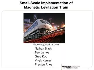
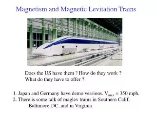
Introduction • Maglev suspension technology can be used in high speed train applications • Maglev suspension allows trains to accelerate to over 300 mph and reduces maintenance by almost eliminating moving parts
Previous Work • Dr. Sam Gurol and Dr. Post have worked on “The General Atomics Low Speed Urban Maglev Technology Development Program” utilizing the rotary track method
Previous Work Cont. • Dr. Richard Post was the head scientist for the magnetic levitation program at Lawrence Livermore National Laboratory • Pioneered the Inductrack method of magnetic levitation in the 1990’s • Inductrack method has been researched by NASA as a means to launch rockets
Previous Work Cont. • Work by Paul Friend in 2004 • Levitation Equations • Matlab GUI • Work by Glenn Zomchek in 2007 • Design of system using Inductrack method • Successful levitation to .45 mm.
Previous Set-Up Displacement sensor DC motor Halbach array magnet device Inductrack Wheel Set up used in previous year’s project
Project Summary • The goals of our project are: • Improve upon system used in previous years • Demonstrate successful levitation • Design and implement closed loop control of levitation height
Complete System Block Diagram Figure 2: Complete System Block Diagram
Physics of Halbach Array Magnets • Designed by Klaus Halbach • Creates a strong, enhanced magnetic field on one side, while almost cancelling the field on the opposite side • Peak strength of the array: B0=Br(1-e-kd)sin(π/M)/(π /M) Tesla k = 2π/λ, M = # of magnets, Br = magnet strength, d = thickness of each magnet
Physics of the Inductrack • Halbach array moving at velocity v m/sec over inductrack generates flux φ0sin(ωt), φ0 Tesla-m2, linking the circuit ω = (2π/λ)v rad/sec • Voltage induced in inductrack circuit: V(t) = ω φ0cos(ωt) • Inductrack R-L circuit current equation: V(t) = L*di(t)/dt + R*i(t)
Physics of the Inductrack Cont • Close-packed conductors, made utilizing thin aluminum or copper sheets • Allows for levitation at low speeds • Can be modeled as an RL circuit • Transfer function has pole at -R/L
Physics of the Inductrack Cont. • Dr. Post used the induced current and magnetic field to derive • Lift force: • <Fy> = Bo2w2/2kL*1/1+(R/ωL)2*e-ky1 • Drag force: • <Fx> = Bo2w2/2kL* (R/ωL) /1+(R/ωL)2*e-ky1 Where y1 is the levitation height in meters
Physics of the Inductrack Cont. • Phase shift relates to drag and levitation forces • Lift/Drag = ω*L/R • To maximize lift, a large amount of inductance and low resistance is desired • L = μ0 w/(2kdc) , where dc is the center to center spacing of conducting strips and w is the track width • Equation shows that we want the narrow transverse slots on the track as wide and close together as possible to maximize L
Physics of the Maglev System • Force needed to levitate: F = m*9.81 Newtons • Breakpoint velocity: • By solving Lift/Drag for v, vb=λω/(2π) m/sec
Functional Requirements • Rotary Wheel Requirements: • A new wheel shall be fabricated with a radius of 9 inches. • A new aluminum Inductrack shall be fabricated with 4 to 5 mm conducting strips with 0.5 mm spacing between the strips. • Maglev Device Requirements: • Two new devices shall be fabricated out of balsa wood to house the Halbach arrays. • The device shall have a breakpoint levitation velocity of less than 30 m/s, corresponding to a motor speed of 1253 RPM.
Functional Requirements Cont. • Halbach Array Requirements: • 6 mm cube magnets shall be used to create the Halbach arrays. • Each magnet shall have peak strength of 1.21 Tesla. • A Halbach array of 5 by 5 magnets shall be constructed using 6mm cube magnets. • The length of the Halbach array shall be 34 mm. • The width of the Halbach array shall be 34 mm. • The total area under the Halbach array shall be 1156 mm2. • The wavelength of the Halbach array shall be 28 mm. • The Halbach array peak strength shall be 0.80595 Tesla.
Functional Requirements Cont. • Another Halbach array of 5 by 13 shall be constructed. • The length of the Halbach array shall be 90 mm. • The width of the Halbach array shall be 34 mm. • The total area under the Halbach array shall be 3060 mm2. • The wavelength of the Halbach array shall be 28 mm. • The Halbach array peak strength shall be 0.80595 Tesla.
Functional Requirements Cont. • Performance Specifications • The controller to be used has yet to be determined. • The maximum overshoot of the system shall be <10%. • The steady state error shall be less than 0.2 cm. • The rise time shall be less than13.9 ms. • The settling time shall be less than 55.6 ms.
Preliminary Lab Work • Checked Glenn Zomchek’s equations • Checked equations against Paul Friend’s GUI • Ordered Magnets • Determined and indicated polarity of magnets • Determined specifications for initial testing
Equipment List • 9” radius polyethylene wheel, with a width of 2” • 80 - 6mm cube neodymium magnets • 2 balsa wood structures to house the 5x5 Halbach array and the 5x13 Halbach array • Structure to hold Halbach Array device that enables it to levitate • 1 – 57”x2” sheet of thin conducting strips • Reliance motor model 437698-KW • D&D ES-10E-33 DC motor • Motor Controller (TBD) • Digital Force Gauge Model: 475040 • Displacement Transducer Model: MLT002N3000B5C
Schedule of Tasks • Before winter break: • Design of wheel with 9” radius and send design for fabrication on campus • Design of track and research for fabrication off campus • Design of balsa wood device for fabrication • Research and ordering of new controller for easier closed loop control. New controller will control armature voltage only, keeping field voltage constant
Schedule of Tasks Cont. • Week 1 – install system will all new fabricated parts • Week 2 – modeling of the current motor for open loop testing with the new wheel and Halbach array • Weeks 3 & 4 – testing of system for levitation • Week 5 - compare simulation results with experimental results
Schedule of Tasks Cont. • Weeks 6 & 7 – Testing and modeling of new motor and Halbach array system • Weeks 8 & 9 – Design of closed loop controller for Halbach array system • Week 10 – Testing of the closed loop system • Week 11 – Student expo
Schedule of Tasks Cont. • Week 12 – Preparation of senior project presentation • Week 13 – Preparation of senior project report • Week 14 – Senior Project Presentations
Richard F. Post Magnetic Levitation System for Moving Objects U.S. Patent 5,722,326 March 3, 1998 Richard F. Post Inductrack Magnet Configuration U.S. Patent 6,633,217 B2 October 14, 2003 Richard F. Post Inductrack Configuration U.S. Patent 629,503 B2 October 7, 2003 Richard F. Post Laminated Track Design for Inductrack Maglev System U.S. Patent Pending US 2003/0112105 A1 June 19, 2003 Coffey; Howard T. Propulsion and stabilization for magnetically levitated vehicles U.S. Patent 5,222,436 June 29, 2003 Coffey; Howard T. Magnetic Levitation configuration incorporating levitation, guidance and linear synchronous motor U.S. Patent 5,253,592 October 19, 1993 Levi;Enrico; Zabar;Zivan Air cored, linear induction motor for magnetically levitated systems U.S. Patent 5,270,593 November 10, 1992 Lamb; Karl J. ; Merrill; Toby ; Gossage; Scott D. ; Sparks; Michael T. ;Barrett; Michael S. U.S. Patent 6,510,799 January 28, 2003 Applicable Patents
Works Consulted • Glenn Zomchek. Senior Project. “Redesign of a Rotary Inductrack for Magnetic Levitation Train Demonstration.” Final Report, 2007. • Paul Friend. Senior Project. Magnetic Levitation Technology 1. Final Report, 2004. • Gurol, Sam. E-mail (Private Conversation) • Post, Richard F., Ryutov, Dmitri D., “The Inductrack Approach to Magnetic Levitation,” Lawrence Livermore National Laboratory. • Post, Richard F., Ryutov, Dmitri D., “The Inductrack: A Simpler Approach to Magnetic Levitaiton,” Lawrence Livermore National Laboratory. • Post, Richard F., Sam Gurol, and Bob Baldi. "The General Atomics Low Speed Urban Maglev Technology Development Program." Lawrence Livermore National Laboratory and General Atomics.