Download
1 / 39
430 likes | 945 Vues
Closed Loop Magnetic Levitation Control of a Rotary Inductrack System. Students: Austin Collins Corey West Advisors: Mr . S. Gutschlag Dr. Y. Lu Dr. W. Anakwa. 1. Presentation Outline. I. Introduction Background and Previous Work Original Goals

E N D
Closed Loop Magnetic Levitation Control of a Rotary Inductrack System Students: Austin Collins Corey West Advisors: Mr. S. Gutschlag Dr. Y. Lu Dr. W. Anakwa 1
Presentation Outline I. Introduction • Background and Previous Work • Original Goals • System Block Diagram II. Current Progress • Analog Circuitry • Controller • Status of the Project III. Conclusion • Patents • References • Questions 2
Halbach Array of Magnets Figure 3-1 3
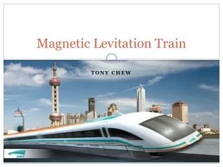
Halbach Array in an Actual Bullet Train 4 Figure 4-1
Inductrack System without and with Safety Enclosure Figure 5-2 Figure 5-1 5
Copper Inductrack Rail Figure 6-1 6
Magnetic Field Interaction Figure 7-1 Figure 7-2 7
Relevant Equations Equation 8-1 Equation 8-2 8
Common DC Motor Circuit Schematic Figure 9-1 9
Motor Model Figure 11-1 11
Objectives • Selection of suitable platform for controller implementation, which will allow a user to enter desired levitation height. • Use of the selected platform to generate a PWM signal to drive the power electronics. • Design system to be autonomous. • Selection and design of appropriate power electronics which will allow control of the PWM signal. 12
Controller Transfer Function Using Matlab Design Specification 1: steady state error = 0 Design Specification 2: Less than 10% overshoot. ζ = 0.707 Design Specification 3: ts < 6 seconds Figure 13-1 13
Converting Continuous Time Controller to Discrete Time Equation 14-1 Equation 14-1 14
Closed Loop Control Simulation 15 Figure 15-1
Displacement Figure 16-1 16
Angular Velocity Figure 17-1 17
Control Voltage Figure 18-1 18
Discrete Time Controller Equation 19-1 19
Xilinx Blockset Figure 20-1 20
Xilinx Blockset Figure 21-1 21
Xilinx Blockset Simulation Figure 22-1 22
Xilinx Blockset Simulation Figure 23-1 23
Xilinx Blockset Simulation Figure 24-1 24
High Level Block Diagram 25 25 Figure 25-1
Controller Flowchart 26 Figure 26-1
Performance Specifications for Controller • The controller platform selected is a Spartan 3E FPGA board. • The controller shall sample displacement at least every 10 ms. • The controller shall generate PWM control signal within 10 ms. 27
Controller Simulation Figure 28-1 28
Experimental Data for Look-Up Table Figure 29-1 Figure 29-2 29
Converting Electrical Frequency to Displacement m Equation 30-1 rad/s Equation 30-2 30
Preliminary PWM Flowchart Figure 31-1 31
FPGA PWM Results 32 Figure 32-1
Analog Circuit Schematic Figure 33-1 33
Application of Circuit with Pittman Motor 34 Figure 34-1
Analog Circuit Results Figure 35-1 Figure 35-2 Figure 35-3 35
Status of the Project 36 Figure 36-1
Status of the Project • Analog Circuitry • Controller • VHDL Modules 37
Patents •Coffey; Howard T. Propulsion and stabilization for magnetically levitated vehicles U.S. Patent 5,222,436 June 29, 2003 •Coffey; Howard T. Magnetic Levitation configuration incorporating levitation, guidance and linear synchronous motor U.S. Patent 5,253,592 October 19, 1993 •Levi;Enrico; Zabar;Zivan Air cored, linear induction motor for magnetically levitated systems U.S. Patent 5,270,593 November 10, 1992 •Richard F. Post Magnetic Levitation System for Moving Objects U.S. Patent 5,722,326 March 3, 1998 •Richard F. Post Inductrack Magnet Configuration U.S. Patent 6,633,217 B2 October 14, 2003 •Richard F. Post Inductrack Configuration U.S. Patent 629,503 B2 October 7, 2003 •Richard F. Post Laminated Track Design for Inductrack Maglev System U.S. Patent Pending US 2003/0112105 A1 June 19, 2003 •Lamb; Karl J. ; Merrill; Toby ; Gossage; Scott D. ; Sparks; Michael T. ;Barrett; Michael S. U.S. Patent 6,510,799 January 28, 2003 38
References • Kyle Gavelek, Victor Panek, Christopher Smith. Senior Project. “Closed Loop Control of Halbach Array Magnetic Levitation System Height”. Final Report, May 2013. • Dirk DeDecker, Jesse VanIseghem. Senior Project. “Development of a Halbach Array Magnetic Levitation System”. Final Report, May 2012. • Glenn Zomchek. Senior Project. “Redesign of a Rotary Inductrack for Magnetic Levitation Train Demonstration”. Final Report, May 2007. • Paul Friend. Senior Project. Magnetic Levitation Technology 1. Final Report, May 2004. • Post, Richard F., Ryutov, Dmitri D., “The Inductrack Approach to Magnetic Levitation,” Lawrence Livermore National Laboratory. 39